How To Design An Automatic Seat Warmer For Your Sofa?
The concept of heated seats is adopted by almost every automobile company these days and in every latest model of Toyota, Honda, KIA, etc, the company is offering heated seats in the cars. Most of the companies provide heated as well as cold seats in their models that make the driving experience very comfortable especially in summers. Keeping this idea in view I thought why not implement the idea of heated seats at our homes on our Sofa that is placed in the living room or somewhere else. The circuit that I will design later on in this article will be responsible for heating every type of sofa whether it be round arm sofa, square arm, hard wedge, etc. The circuit will be placed at the lower side of the sofa and the seats will automatically start heating after some time intervals. Now, without wasting a second let’s get to work.
How To Attach Heating Plates With Arduino?
Now, we will gather information regarding the electronic components before making a list of all the hardware components because no one will want to stick in the middle of a project just because of a missing component.
Step 1: Components Needed (Hardware)
Step 2: Components Needed (Software)
- Proteus 8 Professional (Can be downloaded from Here)
Step 3: Working Principle
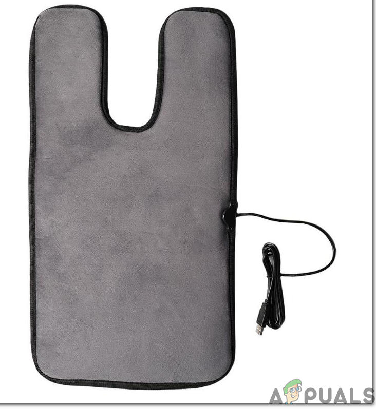
The working principle of this project is quite simple. It is powered by the 12V Lipo battery. The Lipo battery is preferred in this project because it gives a good backup and it will provide a backup time of approximately 2 days or even more. An AC to DC adapter can also be used to power this circuit because our requirement is 12V DC. The backbone of this project are the Heating Plates that will be responsible for heating the sofa. The temperature will sense the temperature of the room and when the temperature falls below the limit that is set in the code the Relay module will be triggered and the heating will start. The heating will continue until the temperature is returned to its previous state. The Relay will be triggered when the temperature will fall below 25 Degrees and it will be turned OFF when the temperature is returned to its original position. The code can be altered according to your requirement and I have attached the code below so, that you can understand it and make the alterations if you want to.
Step 4: Simulating The Circuit
Before making the circuit it is better to simulate and examine all the readings on a software. The software we are going to use is the Proteus Design Suite. It is a software on which electronic circuits are simulated.
- After you download and install the Proteus software, open it. Open a new schematic by clicking the ISIS icon on the menu.
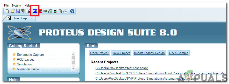
ISIS - When the new schematic appears, click on the P icon on the side menu. This will open a box in which you can select all the components that will be used.
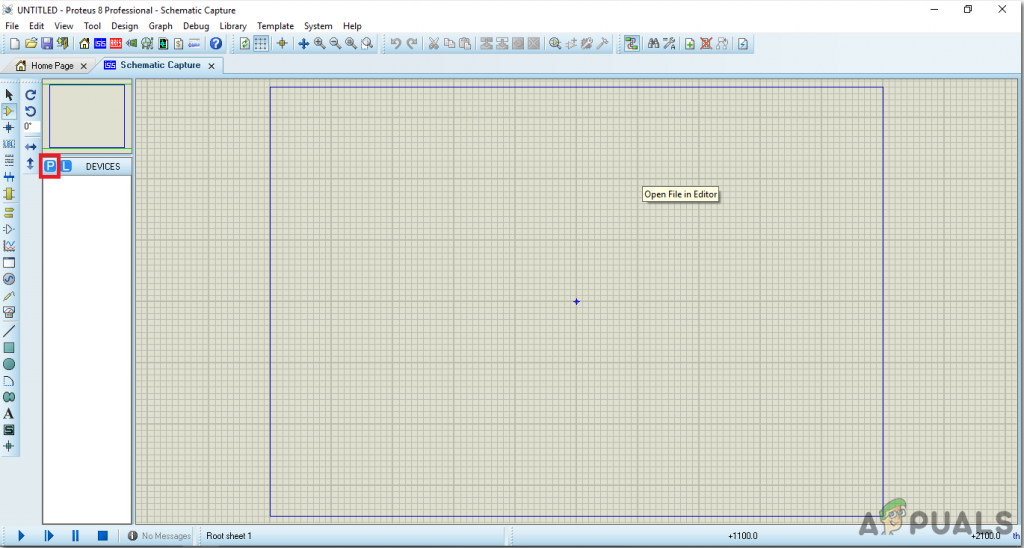
New Schematic - Now type the name of the components that will be used to make the circuit. The component will appear in a list on the right side.
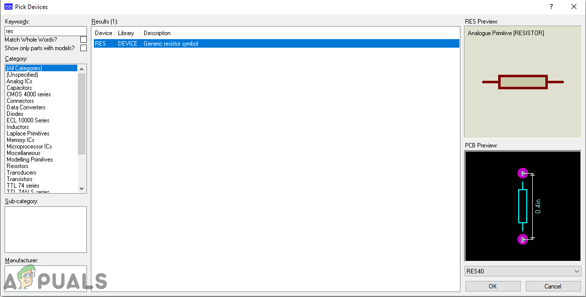
Selecting Components - In the same way, as above, search all the components. They will appear in the Devices List.
After simulating the circuit we came to know that it is working fine, hence we will proceed a step ahead and design its PCB layout.
Step 5: Make A PCB Layout
As we are going to make the hardware circuit on a PCB, We need to make a PCB layout for this circuit first.
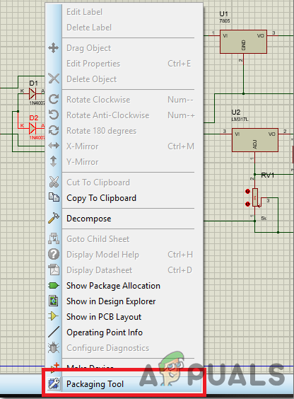
- To make the PCB layout on Proteus, we first need to assign the PCB packages to every component on the schematic. To assign packages, right-click on the component you want to assign the package and select the Packaging Tool.
Assign Packages - Click on the ARIES option on the top menu to open a PCB schematic.
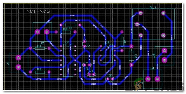
ARIES Design - From the Components List, Place all the components on the screen in a design you want your circuit to look like.
- Click on the track mode and connect all the pins that the software is telling you to connect by pointing an arrow.
Step 6: Circuit Diagram
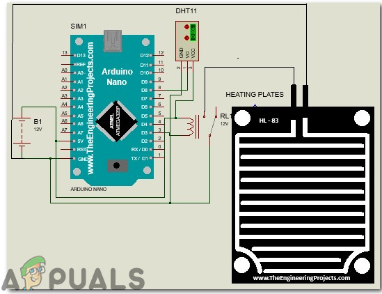
After making the PCB layout the circuit diagram will look like this:
Step 7: Getting Started With Arduino
If you haven’t worked on Arduino IDE before, don’t worry because a step by step to set up Arduino IDE is shown below.
- Download the latest version of Arduino IDE from Here.
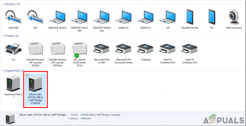
- Connect your Arduino board to the PC and open Control Panel. Click on Hardware and Sound. Now open Devices and Printer and find the port to which your board is connected. In my case it is COM14 but it is different in different computers.
Finding Port - Click on the Tool menu and set the board as Arduino Nano (AT Mega 328P).
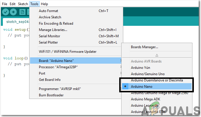
Setting The Board - In the same Tool menu, set the Processor as ATmega328p (Old Bootloader).
- Download the code attached below and paste it into your Arduino IDE. Click on the upload button to burn the code on your microcontroller.
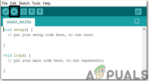
Upload The Code
Download the code and necessary libraries by clicking Here.
Step 8: Understand The Code
The code used in this project is very simple and well commented. Although it is self-explanatory, it is briefly described below so that if you are using a different Arduino board like Uno, mega, etc you can modify the code properly and then burn it onto your board.
- At the start, the library to use DHT11 is included, variables are initialized to store the temporary values during the run time. Pins are also initialized to connect the sensors to the microcontroller.
#include <dht11.h> // including library to use temmperature sensor
dht11 DHT11; // creating object for temperature sensor
#define dhtpin 8 // initialize pin to connect the sensor
#define relay 3 // initialize pin to connect the relay
float temp; // variable to hold temporary value
2. void setup() is a function that is executed only once in the code when the microcontroller is powered up or the enable button is pressed. The baud rate is set in this function which is basically the speed in bits per second by which the microcontroller communicates with the peripheral devices.
void setup(){
pinMode(dhtpin,INPUT); // use this pin as INPUT
pinMode(relay,OUTPUT); // use this pin as OUTPUT
Serial.begin(9600); // setting baud rate
}
3. void loop() is a function that is executed again and again in a loop. In this function, we are reading the data from the output pin of DHT11 and switching the relay on or off at a certain temperature level. If the temperature is less than 25 degrees, the heating plates will turn on otherwise they will remain turned off.
void loop(){
delay(1000); // wati for a second
DHT11.read(dhtpin); // read thw temperature
temp = DHT11.temperature; // save the temperature in variable
Serial.print(temp); // print the value on monitor
Serial.println("C ");

if(temp<=25) // Turn the heating plates on
{
digitalWrite(relay,LOW);
//Serial.println(relay);
}
else // Turn the heating plates off
{
digitalWrite(relay,HIGH);
//Serial.println(relay);
}
}
Step 9: Setting Up The Hardware
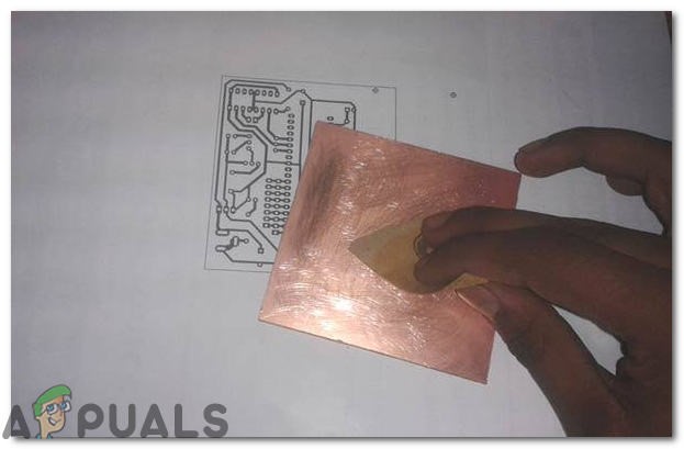
As we have now simulated the circuit on software and it is working perfectly fine. Now let us move ahead and place the components on PCB. A PCB is a printed circuit board. It is a board fully coated with copper on one side and fully insulating from the other side. Making the circuit on the PCB is comparatively a lengthy process. After the circuit is simulated on the software, and its PCB layout is made, the circuit layout is printed on a butter paper. Before placing the butter paper on the PCB board use the PCB scrapper to rub the board so that the copper layer on board is diminished from top of the board.
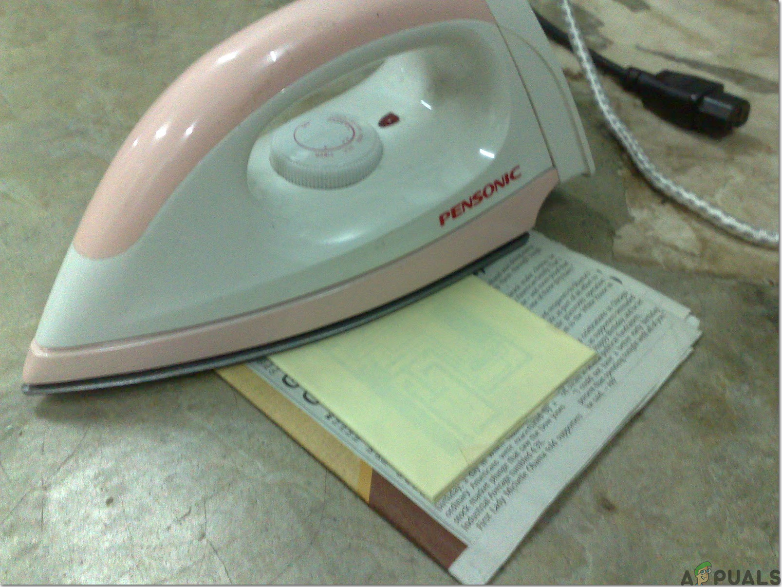
Then the butter paper is placed on the PCB board and ironed until the circuit is printed on the board (It takes approximately five minutes).
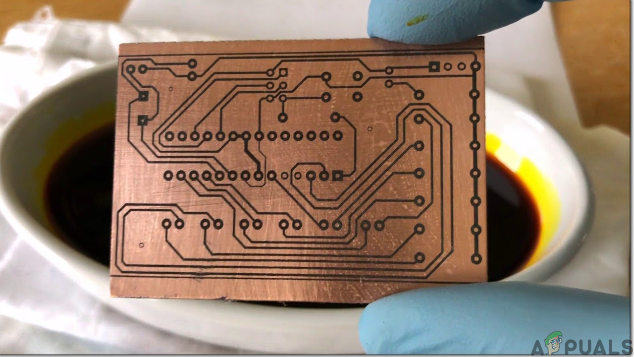
Now, when the circuit is printed on the board, it is dipped into the FeCl3 solution of hot water to remove extra copper from the board, only the copper under the printed circuit will be left behind.
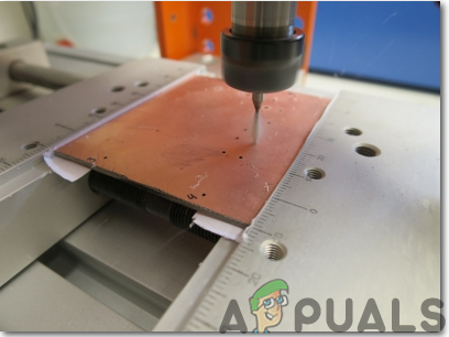
After that rub the PCB board with the scrapper so the wiring will be prominent. Now drill the holes in the respective places and place the components on the circuit board.
Solder the components on the board. Finally, check the continuity of the circuit and if discontinuity occurs at any place de-solder the components and connect them again. In electronics, the continuity test is the checking of an electric circuit to check whether current flow in the desired path (that it is in certainty a total circuit). A continuity test is performed by setting a little voltage (wired in arrangement with a LED or commotion creating part, for example, a piezoelectric speaker) over the picked way. If the continuity test passes, it means that the circuit is adequately made as desired. It is now ready to be tested. It is better to apply hot glue using a hot glue gun on the positive and negative terminals of battery so that the terminals of the battery may not be detached from the circuit.
Step 10: Testing The Circuit
After assembling the hardware components on the PCB board and checking the continuity we need to check whether our circuit is working properly or not we will test our circuit. After switching ON the circuit place it near to the place where the temperature is below 25 Degrees. You will observe that the plates will start heating and they will be turned OFF as soon as the temperature rises. After testing the circuit place it inside a covering. Covering can be designed at home using any material. For example, a wooden covering can be designed, a plastic casing can be designed or a circuit can also be placed inside a thick cloth and stitched. Then stick it at the bottom side of your sofa using double tape. Regularly monitor the battery and charge it frequently.
That’s all for today. Keep on visiting our website for more interesting engineering projects and don’t forget to share your experience after making this project at your home.


