How To Make An Automated Fan To Prevent Electronic Devices From Heating?
We are living in an era where everything is controlled by computers or microcontrollers. Continuous work makes these electronic devices hot. We can make an automated fan that will automatically switch on when the temperature rises to a certain level. This project can be implemented on any scale.
This system includes an Arduino board and a temperature sensor. A temperature sensor will sense the temperature and automatically switch the fan on or off.
How to Automate a temperature-dependent fan using Arduino?
As we now know what we are going to do, let’s collect some more information to start working on our project.
Step 1: Gathering the Components
The best approach to start any project is to make a list of all the components at the start and a good plan to work on it. The following are the components that we are going to use in this project.
- No products found.
- No products found.
- No products found.
- Fan
- No products found.
- No products found.
- No products found. (if using Veroboard)
- No products found. (if using Veroboard)
Step 2: Studying the Components
Now, as we know what components we are going to use, let us move one step ahead and study the working of these components briefly.
Arduino nano is a microcontroller board that is used to control or carry out different tasks in a circuit. A, C Code is needed to tell the microcontroller board how and what operations to perform. Arduino Nano has exactly the same functionality as Arduino Uno but in quite a small size. the microcontroller on the Arduino Nano board is ATmega328p. We can also use Arduino UNO for implementing the project.
DHT11 is a temperature and humidity sensor. Its temperature range is 0 to 50-degree Celsius. It is a low cost and an efficient sensor that gives high stability. To measure the temperature it has a built-in thermistor. It also measures the humidity but in this project, we don’t need to measure humidity.
A relay module is a switching device that takes input from Arduino and switches accordingly. It operates in two modes, Normally Open (NO) and Normally Closed (NC).
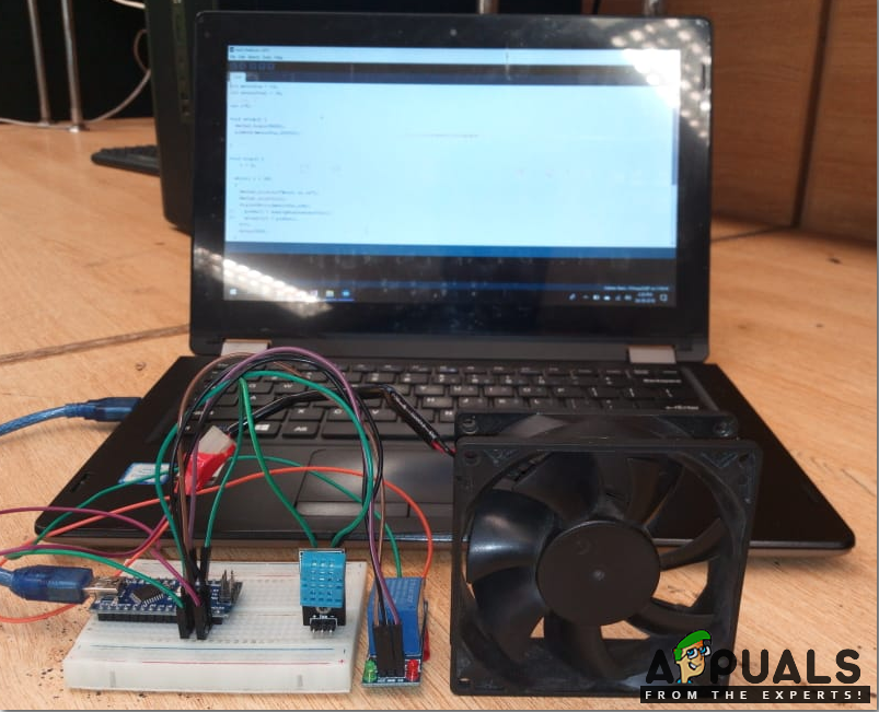
Step 3: Assembling the circuit
Now let us move ahead and assemble the circuit. Connect the Vcc and ground pin of the DHT11 sensor to the 5V and ground of the Arduino nano. Connect the output pin of the DHT11 sensor to the Pin2 and the IN pin of the relay module to the Pin3 of the Arduino. Power up the relay module through Arduino and connect the positive wire of the fan in the NO pin of the relay module. I am using breadboard here but you can also use Veroboard. If you use a Veroboard make sure that you solder the female headers on the board to insert the Arduino nano board and the DHT sensor in it. And don’t forget to carry out a continuity test to check if any connection is short.
There is one thing very important that must be kept in mind that the DHT sensor should be close to the device that is to be cooled by the fan.
Step 4: Getting started with Arduino
If you are not already familiar with the Arduino IDE, don’t worry, you are explained how to use Arduino IDE below.
- Download the latest version of Arduino IDE from Arduino
- Connect the Arduino board to your PC and go to Control Panel >Hardware and Sound >Devices and Printers. Here, find the port to which your Arduino is connected. In my case it is COM14 but it is different on different computers.
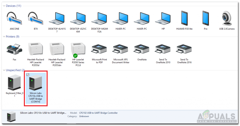
Finding Port - Click on Tools and set your board to Arduino Nano.
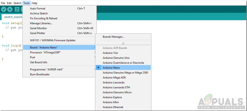
Setting board - From the same Tool menu, set the Processor to ATmega328p (Old Bootloader).
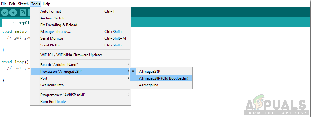
Setting Processor - Now set the port that you observer back in the control panel.
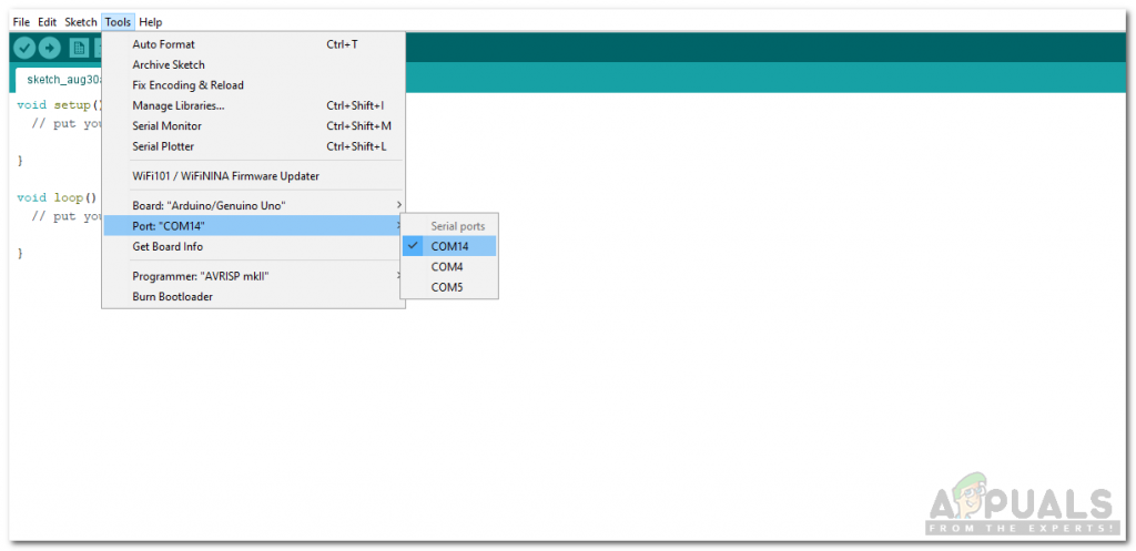
Setting Port - We will have to include a library to use the DHT11 sensor. The library is attached below in the download link along with the code. Go to Sketch > Include Library > Add .ZIP Library.
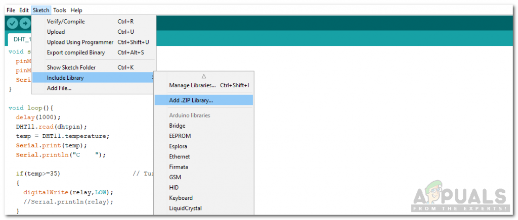
Including Library - Download the code attached below and copy it to your IDE. Click on the upload button to burn the code in your microcontroller board.

Upload
You can download the code from Here
Step 5: Code
The code for the DHT11 sensor is really simple but here is some explanation of the code.
- At the start, the library to use DHT11 is included, variables are initialized and pins are also initialized.
#include <dht11.h>
dht11 DHT11;
#define dhtpin 2
#define relay 3
float temp;
2. void setup() is a function that is used to set the pins as INPUT or OUTPUT. It also sets the baud rate of the Arduino. Baud rate is the communication speed of the microcontroller board.
void setup(){
pinMode(dhtpin,INPUT);
pinMode(relay,OUTPUT);
Serial.begin(9600);
}
3. void loop() is a function that runs again and again in a cycle. In this function, we are reading the data from the output pin of DHT11 and switching the relay on or off at a certain temperature level.
void loop(){
delay(1000);
DHT11.read(dhtpin);
temp = DHT11.temperature;
Serial.print(temp);
Serial.println("C ");

if(temp>=35) // Turn the fan on
{
digitalWrite(relay,LOW);
//Serial.println(relay);
}
else // Turn the fan off
{
digitalWrite(relay,HIGH);
//Serial.println(relay);
}
}
Similar Applications
We are using this temperature sensor for the switching of a fan for electrical devices. It can also be used for other purposes, some of its applications are as follows.
- Maintaining a constant Warm temperature for chickens in a poultry hut.
- Smart Homes.
- Fire Alarm circuits.
Now as you have learned how to automate the fan to cool down your electrical devices, you can now start working on this project and you can also use this DHT sensor in other applications.


hey, i did every step you said above , the fan wont turn on ,no matter what threshold i put , the fan will keep working