How to Design A Touch Dimmer Circuit Using Arduino?
A switch is the most essential part of any circuit. Different circuits use different switches in them. In this project, we are going to use a Touch Dimmer Switch. This switch is a touch-sensitive sensor that detects the physical touch or proximity. The electrical appliance which will be controlled by this touch dimmer switch will change its intensity according to the output of this switch.
How to switch a device using Touch Sensor?
Let us start working on our project without wasting any time.
Step 1: Collecting the Components
If you want to avoid any inconvenience in the middle of a project, the best approach is to make a list of all the components that will be used and going through a brief study of their working. A list of all the components that we are going to use in our project is as follows:
- Arduino Uno
- No products found.
- No products found.
- No products found.
- No products found.
- No products found.
- No products found.
- No products found.
Step 2: Studying the Components
As we know have a list of all the components that we are going to use, let us move a step ahead and go through a brief study of these components.
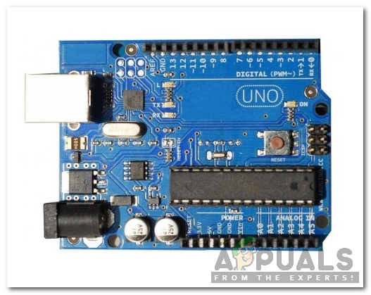
Arduino Uno is a microcontroller board that is used to carry out various operations in different circuits. We burn a C Code on this board to tell it how and what operations to perform.
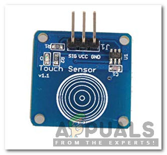
A Touch Sensor is a very sensitive input device that detects physical touch or proximity. The advantage of this sensor is that a single sensor is used to carry out many operations like touch, swipe, pinch, etc. The principle on which it works is, it measures the change in capacitance when a person touches the sensor. This sensor consists of a TTP223 touchpad. When a finger is placed on the sensor, the state of OUT pins shows HIGH.
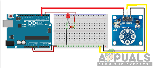
Step 3: Assembling the Components
Now let us assemble all the components and make a switching circuit.
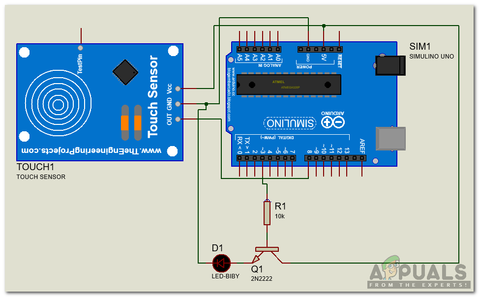
- A touch sensor is a touch-sensitive module which has 3 input/output pins. Power up this module by connecting the Vcc pin and ground pin to the 5V and ground of the Arduino. Connect the SIG or OUT pin of this module to the pin8 of the Arduino.
- Connect the 2N2222 transistor to the pin3 of the Arduino with a resistor connected to the base of the transistor and collector terminal to the 5V of Arduino Uno. Connect a small bulb between the emitter of the transistor and the ground. Pin3 of the Arduino is a PWM pin which means that the value at this pin can be varied from 0 t 255.
Step 4: Getting Started with Arduino
If you are not already familiar with the Arduino IDE, don’t worry because a step by step procedure to set up Arduino IDE is given below.
- Download the latest version of Arduino IDE from Arduino
- Connect your Arduino board to the PC and open Control Panel. Click on Hardware and Sound and View Devices and Printers. Find the name of the port to which your Arduino board is connected.
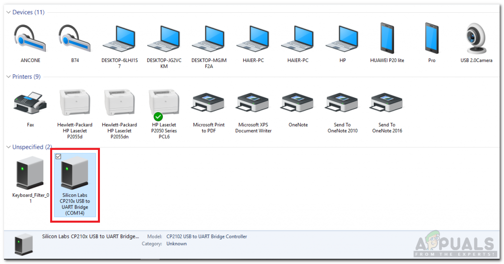
Finding Port - Hover on the Tool menu and set the board to Arduino/Genuino Uno.
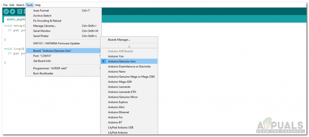
Setting Board - In the same Tool menu, set the port that you observed before in Devices and Printers.
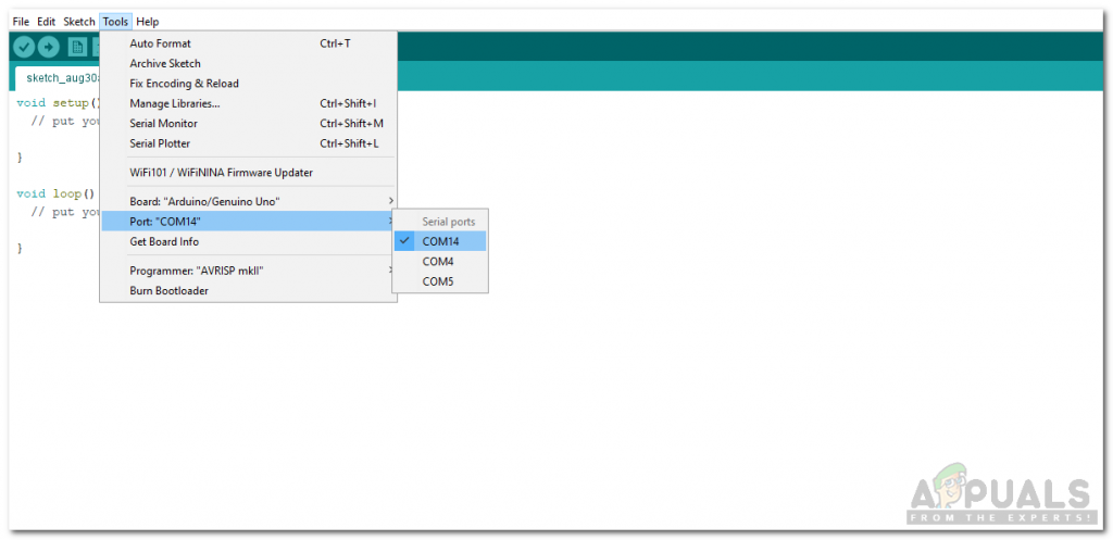
Setting Port - Download the code attached below and click on the upload button to burn the code on the microcontroller board.

Upload
You can download the code by clicking here.
Step 5: Code
The code is very simple. It is explained briefly below:
- At the start, all the pins that will be used are initialized. A variable val is initialized that will contain the value, that will be sent to the bulb to change the intensity of its glow. This value will be from 0 to 255.
int led = 3;
int sen=8;
int val=0;
2. void setup() is a function that is used to set the pins to be used as INPUT or OUTPUT. Baud Rate is also set in this function. Baud rate is the speed by which the microcontroller board communicates with other sensors.
void setup()
{
 Serial.begin(9600);
 pinMode(sen,INPUT);
 pinMode(led,OUTPUT);
 digitalWrite(sen,LOW);
 digitalWrite(led,LOW);
}
3. void loop() is a function which runs repeatedly in a loop. In this loop, it is checked that if the sensor is detecting a finger or not. If the finger is detected continuously, the value in the variable “val” is adjusted to remain between 0 and 255. The process continues until the finger is lifted or the maximum brightness s reached. The controller is programmed if a double tab is detected, it will reduce the brightness.
Similar logic bulb. of PWM is used for the reduction of brightness of the bulb. If the finger is double tabbed, the intensity of the bulb decrees gradually until the finger is lifted or the bulb reaches minimum brightness.
void loop()
{
while(digitalRead(sen)==LOW);

while(digitalRead(sen)==HIGH)
{
 while(digitalRead(sen)==HIGH)
 {
  if(val<=255)
  {
   analogWrite(led,val);
   val++;
   delay(15);
  }
 }
 delay(1000);

 while(digitalRead(sen)==HIGH)
 {
  if(val>=0)
  {
   analogWrite(led,val);
   val--;
   delay(15);
  }
 }
}
}
Now as we know how to integrate the touch sensor with Arduino. Now you can make your own at home and enjoy the dimming of your bulb by using this touch-sensitive sensor.
Applications
The working of the dimmer switch is described above using a small bulb. This process can be implemented in a lot of other applications. Some of these applications are listed below.
- To use the touch dimmer switch with AC incandescent bulbs, dedicated ICs like TT6061A can be used.
- This Touch Dimmer Switch can be used to control the speed of a small fan by simply touching the sensor.
- This Touch Dimmer Switch can be used to control the brightness of a bulb by simply touching the sensor.
- Can replace traditional Dimmer Switches like slide switch or rotary type switch for bulbs.


Thanks for this project. Great work!!!!
Touch dimmer project is working good. It is explained in detail including the program too.
Friends……you can also use small torch bulb too instead of LED ,that will be great.
THANK YOU