How To Make A Simple Fire Alarm Circuit?
In the current structure and designs of buildings like banks, gas stations, and offices, a fire alarm is a basic necessity. They identify the fire in the surrounding at the beginning stage by detecting smoke or warmth and raise an alert which cautions individuals about the fire and furnish adequate time to take precautionary measures. It is not only the cause to prevent big looses to occur but some times it saves many lives just by detecting the fire and alerting the people in the surrounding just by sounding an alarm. In this article, we will study the method to built a simple fire alarm by using a 555 Timer IC. It will detect the fire and sound a buzzer.
A thermistor is the heart of this circuit. This sensor will be used to detect the fire. It is a resistor that is very sensitive to temperature. This means that a small change in temperature will cause a large change in its internal resistance. Its resistance is inversely proportional to the temperature. It means that if the temperature increases, the resistance will decrease and when the temperature decreases, the resistance will increase. An NPN transistor is used as a switch in this circuit.
How To Design A Fire Alarm Circuit?
Now, as we know the main abstract of this project, let us move a step ahead and gather some more information like a component list and working of the circuit, to make the final product.
Step 1: Collecting The Components
The best approach to start any project is to make a list of components and going through a brief study of these components because no one will want to stick in the middle of a project just because of a missing component. A list of components that we are going to use in this project is given below:
- NE555 timer IC
- BC-547 Transistor
- 10k Thermistor
- No products found.
- 100k-ohm Resistor
- 4.7k-ohm Resistor
- 1M-ohm Potentiometer
- 1uF Capacitor
- No products found.
- No products found.
- Connecting wires
- 9V Battery
Step 2: Working Of The Circuit
Pin1 of the 555 Timer IC is the ground Pin. Pin2 of the timer IC is the trigger pin. the second pin of the Timer IC is known as the Trigger Pin. If this pin is directly connected to pin6, it will work in Astable mode. When the voltage at this pin drops below one-third of the total input, it will get triggered. Pin3 of the timer IC is the pin where the output is sent. Pin4 of the 555 Timer Ic is used for the reset purpose. It is initially connected to the positive terminal of the battery. Pin5 of the timer IC is the control pin and it does not have much use. In most of the cases, it is connected to the ground through a ceramic capacitor. Pin6 of the timer IC is named as the threshold pin. pin2 and pin6 are shorted and are connected to pin7 to make it operate in Astable mode. When the voltage of this pin gets greater than two-third of the mains voltage supply, the Timer IC will come back to its stable state. Pin7 of the Timer IC is used for the discharge purpose. The capacitor is given the discharge path through this pin. Pin8 of the timer Ic is directly connected to the ground.
Here, the 555 Timer IC is used in Astable mode. In this mode, an oscillating sound will be produced by the buzzer. So, as this circuit is working in astable mode, the resistor R1 and R2 are used to charge the capacitor C1. The charging process will continue until the voltage is 2/33 Vcc. Then it will start to discharge through R2, till the voltage reaches 1/3 Vcc. the pulse is generated in a way that, while the capacitor is charging, the output pin3 of the 555 timer IC remains HIGH. This pin goes to the OFF state when this capacitor is discharging. A buzzer is connected to the output pin3 of the 555 Timer IC. The buzzer will produce a beep sound when the outputpin3 is high and will remain silent when the output pin3 will be in the OFF state. The frequency generated at the output pin of the timer IC can be adjusted by setting the value of R1 or C.
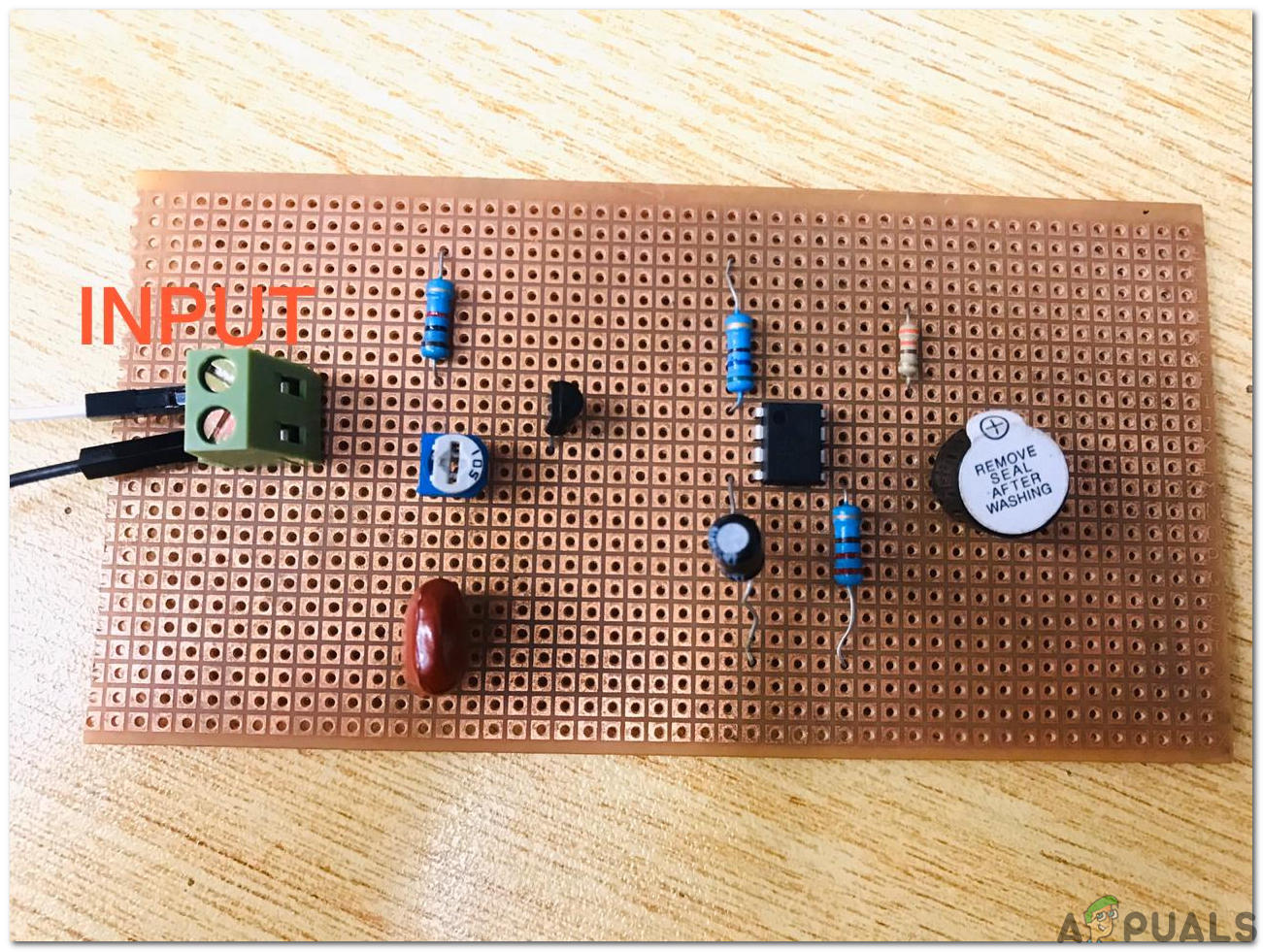
Step 3: Assembling The Components
Now, as we know the main connections and also the complete circuit of our project, let us move ahead and start making the hardware of our project. One thing must be kept in mind that the circuit must be compact and the components must be placed so close.
- Take a Veroboard and rub its side with the copper coating with a scraper paper.
- Now Place the components carefully and close enough so that the size of the circuit does not become very big
- Carefully make the connections using solder iron. If any mistake is made while making the connections, try to desolder the connection and solder the connection again properly, but in the end, the connection must be tight.
- Once all the connections are made, carry out a continuity test. In electronics, the continuity test is the checking of an electric circuit to check whether current flow in the desired path (that it is in certainty a total circuit). A continuity test is performed by setting a little voltage (wired in arrangement with a LED or commotion creating part, for example, a piezoelectric speaker) over the picked way.
- If the continuity test passes, it means that the circuit is adequately made as desired. It is now ready to be tested.
- Connect the battery to the circuit.
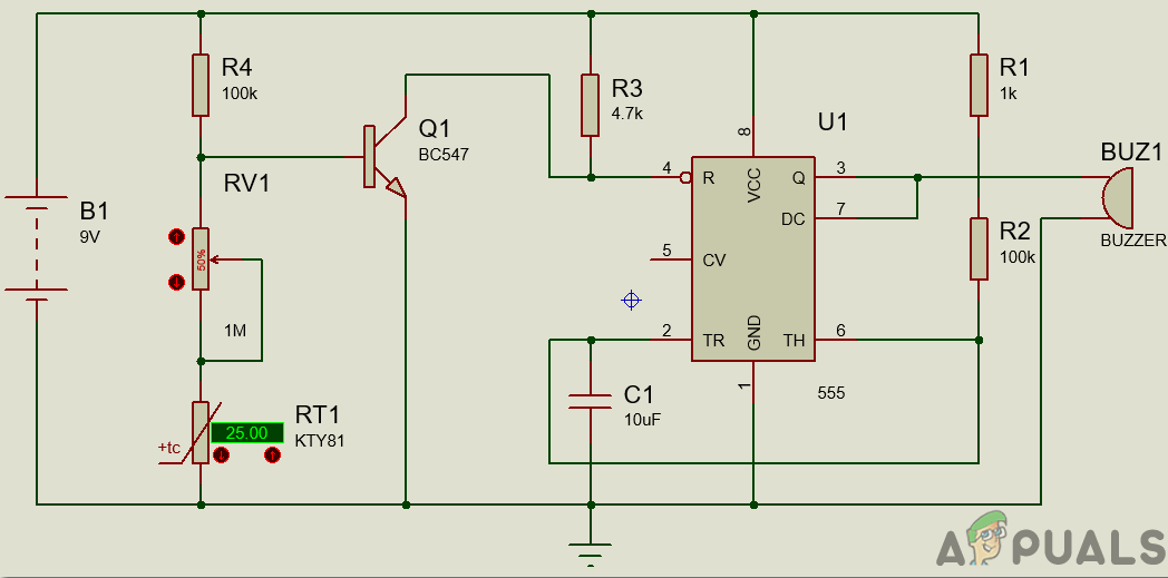
The circuit diagram of this project is given below:
Step 4: Testing
The circuit diagram of this project can be seen in the above section. The thermistor will remain at 10k-ohm when there will be no fire. In this case, as there will be enough voltage across the base-emitter of the transistor, the transistor will remain at ON state. SO, the reset pin of the 555 Timer IC will be connected to the ground because the transistor is in ON state. In this state with the reset pin connected to the ground, the 555 Timer IC will not operate.
Now, when the thermistor is put near the fire. The fire will cause its resistance to decrease. With the decrease in this resistance, the base voltage of the transistor decreases. The transistor will eventually turn OFF when the base voltage decreases its operating voltage. As soon as the transistor goes OFF, the reset pin of the timer IC gets connected to the positive terminal of the battery. As soon as the reset pin goes ON, the buzzer will produce a beep sound.
To turn a transistor ON, a drop of 0.7V is required. So, t make the circuit work according to our wish, we have to adjust the resistance of the potentiometer. So, to adjust this value, first, break the connection of thermistor from the main circuit, and then rotate the knob of the potentiometer. As the potentiometer is grounded at this moment, rotate it until the buzzer sounds. At this point, the buzzer will start producing the beep sound even if a little resistance is lowered. Now connect the thermistor back to its place.


Can you possibly be able to send the .pdsprj file for the same ..as I’m not able to make my circuit work on proteus