Creating a Wireless On/Off Switch For Your PC
A Smart system that controls the lighting, entertainment systems, and other appliances can be designed at home easily and are also the fastest-growing concept of the modern world. Smart Home Systems is a concept in which all the electrical appliances or the devices are controlled using a single remote control. Nowadays, a single component like a relay module can be used to control various electronic parameters of a house, for example, switching of home appliances, monitoring of security alarms, garage door automation, etc. In this project, our Personal Computer will be controlled by an Android Application. In these systems, most of the time, the remote control is a mobile application. As an android mobile is the most common among the people, so an android application is the best option to control our PC.
How To Make a Wireless Switch for Your PC on Mobile Phone?
Step 1: Gathering The Components
To make any project, one must know what the basic components that one is going to need to complete it are. So an excellent approach before starting the work is to make a complete list of all the components to save time and to avoid the chance of getting stuck in the middle of the project. A complete list of all the components that are easily available in the market is given below:
- ESP32
- No products found.
- No products found.
- No products found.
- 5V Relay Module
- Connecting wires
Step 2: Softwares To Be Installed
As we are going to make a wireless switch, we will need a button to turn it on and off. We want to use a mobile phone to operate this button so we will need to develop an application for that. The most convenient application is an android application. We need to install two software to use this application. Both of them are listed below:
Step 3: Installing Android Studio
Before installing Android Studio, we will install JAVA JDK first. To install this, click on the exe file that you downloaded from the above link, and click next until it is successfully installed. Now Go through the following steps so that your command prompt recognizes java as an external or internal command.
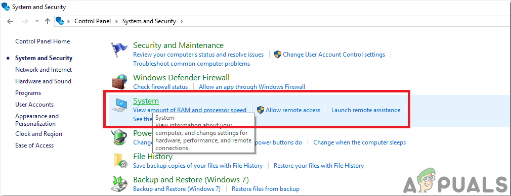
- Open Control Panel and click on System and Security.
- Click on System.
System - Click on Advanced System Setting and then click on Environmental Variables.
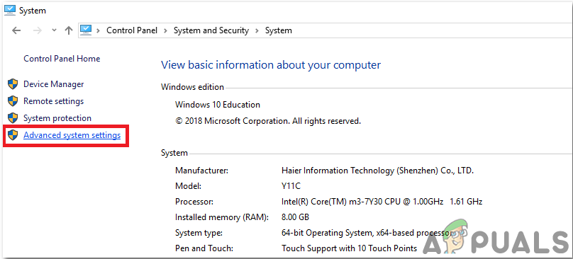
Advanced System Setting - In the System Variable section, click on the path and then click on edit. A new Edit Environmental Variable box will appear.
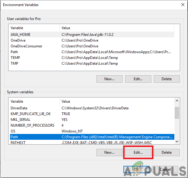
Edit Path - Now go to C:\Program Files\Java in your PC. Open the JDK folder, click on the bin folder and then copy the path of that folder.
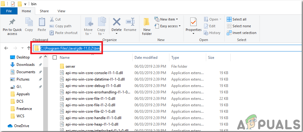
Path of the bin folder - Now go to the Edit Environmental Variable box and click on new to make a new variable. Paste the path that you copied in the above step in the new variable and save it.
- Now to confirm, if it is completely installed, open command prompt and type java –version.
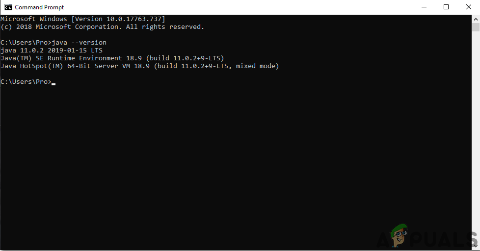
JAVA version
Now as you have successfully installed Java JDK on your computer. Let us now install Android Studio on your computer. Installing this software is very easy. You need to open the downloaded file and click next until your software is fully installed.
Step 4: Connection To Firebase
Now as we have installed Android Studio, let us launch it and make a new project to connect it to the firebase. To do this, follow the following steps.
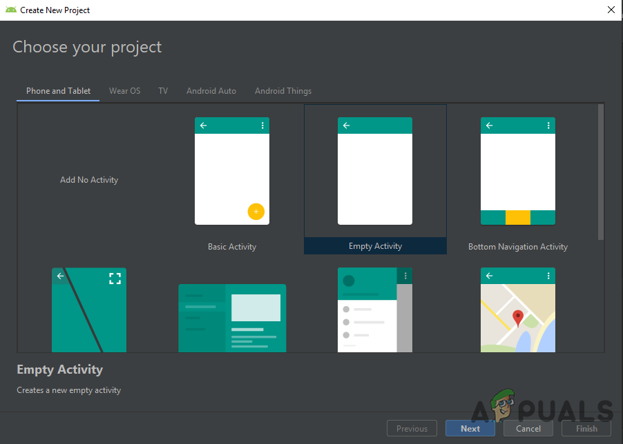
1. Launch Android Studio and make a new project by clicking on the Empty Activity.
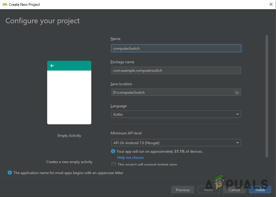
2. Now name your project as computerSwitc, select Kotlin as language, and select the minimum API level according to your mobile phone.
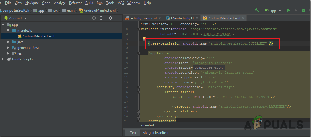
3.Since we are going to use the internet to control the pins of the raspberry pi. We will set permission in our app to access local wifi. To do this, go to app > manifests > AndroidManifest.xml and add the following command.
<uses-permission android:name="android.permission.INTERNET" />
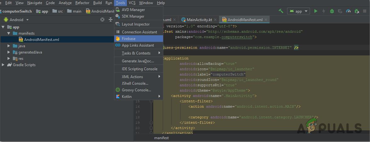
3. Now, click n Tools. A drop-down menu will appear from which, select Firebase.
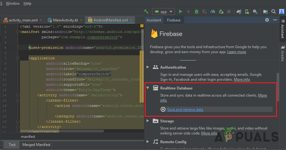
4. A big menu will appear on the right side of the screen that will be providing the menu of almost every service that firebase is providing. But right now our main focus is on Real-Time Database. So click on Real-Time Database. A link to “Save and Retrieve Data” will appear. Click that link.
5. Connect on Connect To Firebase button. It will take you to the default web browser. First, it will ask you to log-in to your Gmail account. Then click on Add the Realtime Database to your app and accept the changes.
6. Now go to Firebase Console. There you will see a project already made. The android logo on that projet’s icon means that it already belongs to an android application.
7. From the Develop menu that appears on the left side of the screen, select Database. A button of Create Database will appear on the right. Click on that button.
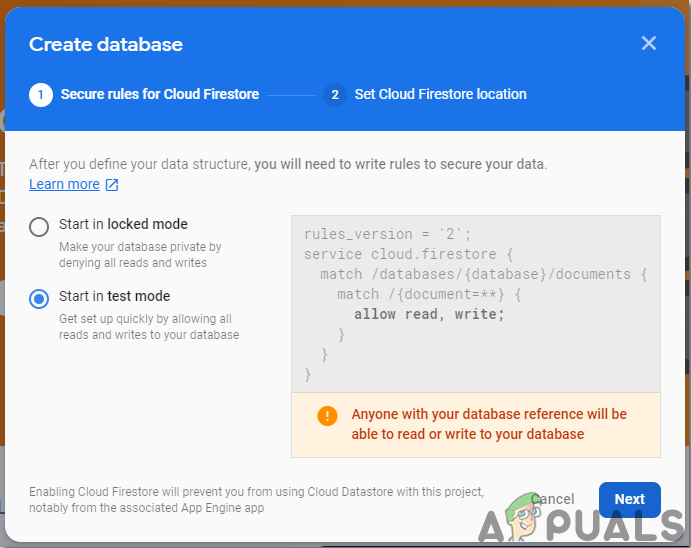
8. A menu will appear asking to set the mode of your database. Click on test mode and then click Enable.
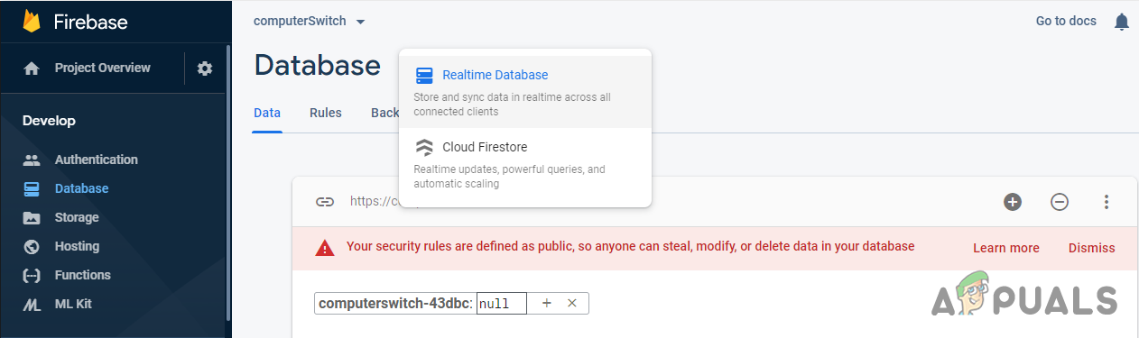
9. Now a really important step to remember is to change the Cloud Firestore to Real-Time Database. To do so click on the button shown in the below image and change the desired option.
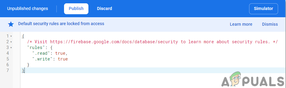
10. Now click on the Rules tab and change the configurations to True. Once everything is done, click Publish.
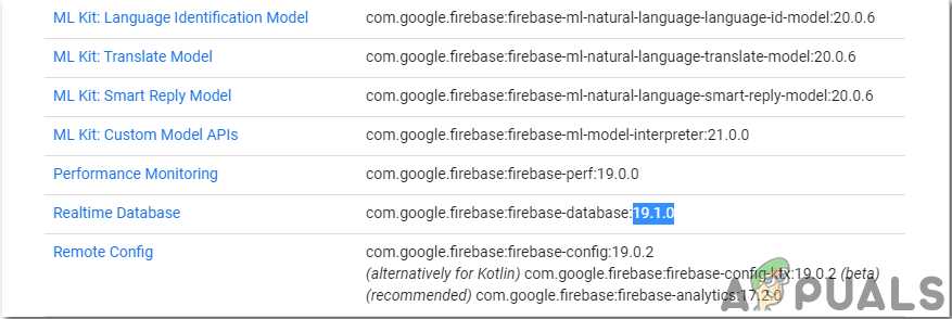
11. One thing that you need to do other than connecting the firebase, is to update the database version. For that, click on go to docs. Now click on guides and select Android Guides from the list that appears on the screen. Scroll down until a table appears. Look for Real-Time Database in that table and find its version. in my case, it is 19.1.0
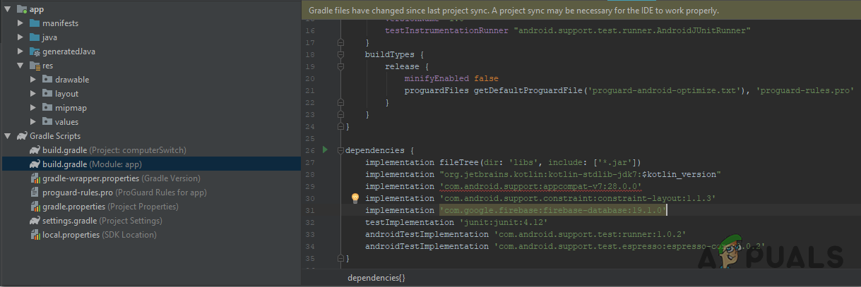
12. Click on Gradle Scripts, a menu on the left side of the screen. Then select built. gradle (Module: app). Now in the code, search for the version of the Real-Time database and replace it by the new one.
13. Now sync the project by clicking on the sync button appearing on the top of the screen.
Step 5: Making Layout
Now, as our android application is connected to the firebase, let us make a layout of our app that will be used by the user to switch the computer on or off. To make a layout, go to app > res > layout > activity_main.xml. where we will design a layout. Copy the code given below there to make a text view.
<?xml version="1.0" encoding="utf-8"?>
<android.support.constraint.ConstraintLayout
        xmlns:android="http://schemas.android.com/apk/res/android"
        xmlns:tools="http://schemas.android.com/tools"
        xmlns:app="http://schemas.android.com/apk/res-auto"
        android:layout_width="match_parent"
        android:layout_height="match_parent"
        tools:context=".MainActivity">
    <Switch
            android:text="Switch"
            android:layout_width="wrap_content"
            android:layout_height="wrap_content"
            android:id="@+id/switch2" app:layout_constraintEnd_toEndOf="parent"
            app:layout_constraintStart_toStartOf="parent" android:layout_marginTop="8dp"
            app:layout_constraintTop_toTopOf="parent" android:layout_marginBottom="8dp"
            app:layout_constraintBottom_toBottomOf="parent"/>
    <TextView
            android:text="Computer Switch"
            android:layout_width="0dp"
            android:layout_height="wrap_content"
app:layout_constraintStart_toStartOf="parent" app:layout_constraintEnd_toEndOf="parent"
android:id="@+id/textView" android:layout_marginTop="8dp"app:layout_constraintTop_toTopOf="parent"
android:layout_marginBottom="8dp" app:layout_constraintBottom_toBottomOf="parent" app:layout_constraintVertical_bias="0.322" android:textSize="36sp" android:textAlignment="center" android:textColor="#000" app:layout_constraintHorizontal_bias="0.0"/> </android.support.constraint.ConstraintLayout>
The layout of our app will look like this:

Step 6: Backend Coding in Kotlin
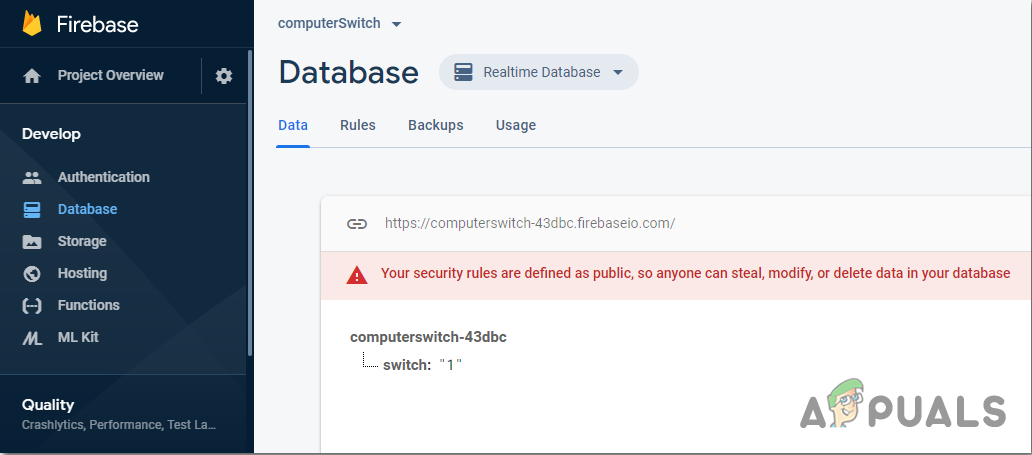
As we have made the frontend of the application, let us move one step ahead and write the backend code to connect it with the firebase. We have connected a toggle switch that will send a 0 to the firebase database when in off state, and it will send a 1 to the firebase database when it is in on state.
Now, on the left corner, click on app > java > com.example.computerswitch > main_activity, and add the following code there in your class. If any error of library occurs, Press ALT+ENTER to include that library automatically.
var database = FirebaseDatabase.getInstance()
var myRef = database.reference
internal lateinit var btnSwitch: Switch

override fun onCreate(savedInstanceState: Bundle?) {
    super.onCreate(savedInstanceState)
    setContentView(R.layout.activity_main)

    btnSwitch = findViewById<View>(R.id.switch2) as Switch

    btnSwitch.setOnClickListener{
        if(btnSwitch.isChecked)
        {
            myRef.child("switch").setValue("1")
        }
        else
        {
            myRef.child("switch").setValue("0")
        }
    }
}
In the below image, you can see that if the switch is turned on, “1” is uploaded to the firebase database. Similarly, a “0” will be replaced here when the switched is turned off.
Step 7: Getting Started With Arduino
If you haven’t worked on Arduino IDE before, don’t worry because a step by step to set up Arduino IDE is shown below.
- Download the latest version of Arduino IDE from Arduino.
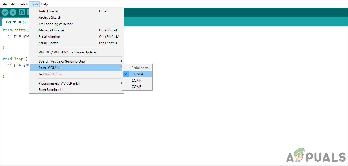
- Connect your Arduino board to the PC and open Control Panel. Click on Hardware and Sound. Now open Devices and Printer and find the port to which your board is connected. In my case it is COM14, but it is different in different computers.
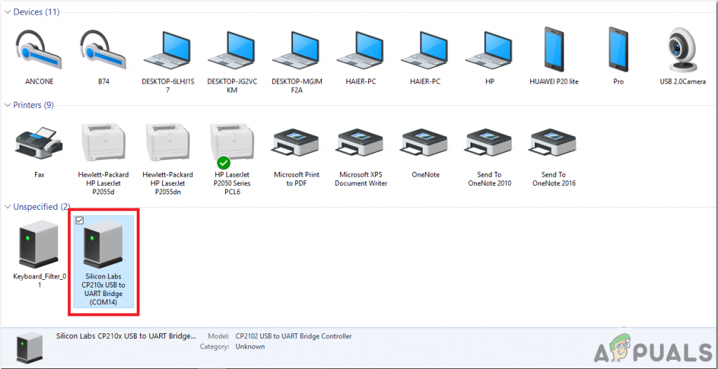
Finding Port - Click on File and then click on Preferences. Copy the following link in the Additional Board Manager’s URL. “https://dl.espressif.com/dl/package_esp32_index.json”
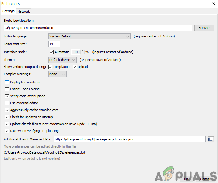
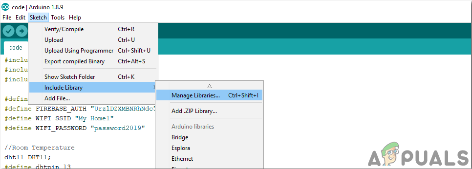
Preferences - Now, to use ESP32 with Arduino IDE, we need to import special libraries that will allow us to burn code on ESP32 and use it. these two libraries are attached in the link given below. To include the library, goto Sketch > Include Library > Add ZIP Library. A box will appear. Find the ZIP folder on your computer and click OK to include the folders.
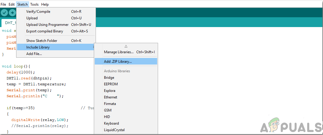
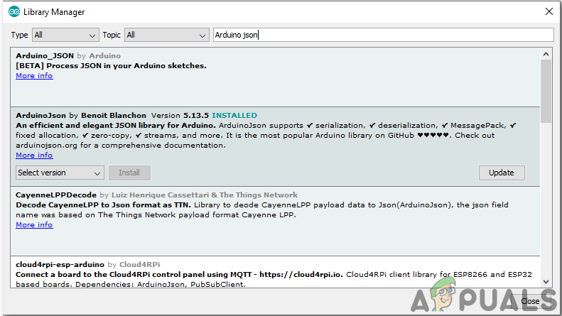
Include Library - Now goto Sketch > Include Library > Manage Libraries.
Manage Libraries - A Menu will open. In the search bar, type Arduino JSON. A list will appear. Install Arduino JSON by Benoit Blanchon.
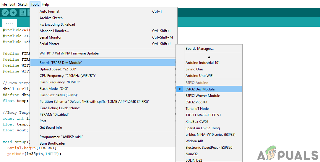
Arduino JSON - Now click on the Tools. A dropdown menu will appear. Set the board to ESP Dev Module.
Setting Board - Click on the Tool menu again and set the port that you observed in the control panel before.
Setting Port - Now Upload the code that is attached in the link below and click on the upload button to burn the code on the ESP32 microcontroller.
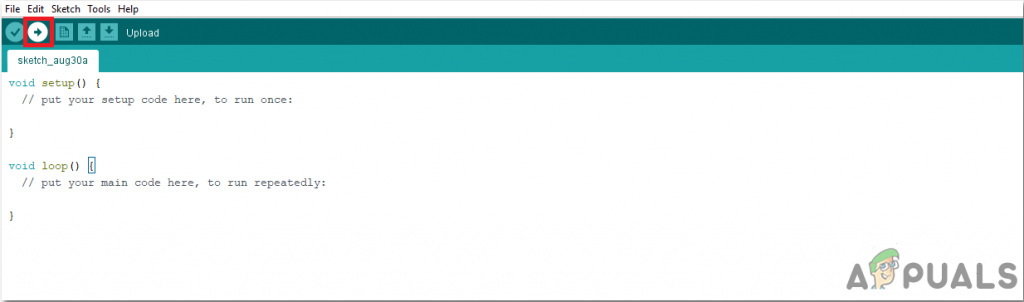
Upload
So now when you will upload the code, an error may occur. This is the most common error that may occur if you are using a new version of the Arduino IDE and the Arduino JSON. The following are the errors that you may see on the screen.
In file included from C:\Users\Pro\Documents\Arduino\libraries\IOXhop_FirebaseESP32-master/IOXhop_FirebaseESP32.h:8:0,

from C:\Users\Pro\Desktop\smartHome\code\code.ino:2:

C:\Users\Pro\Documents\Arduino\libraries\IOXhop_FirebaseESP32-master/IOXhop_FirebaseStream.h:14:11: error: StaticJsonBuffer is a class from ArduinoJson 5. Please see arduinojson.org/upgrade to learn how to upgrade your program to ArduinoJson version 6

StaticJsonBuffer<STREAM_JSON_BUFFER_SIZE> jsonBuffer;

^

In file included from C:\Users\Pro\Documents\Arduino\libraries\IOXhop_FirebaseESP32-master/IOXhop_FirebaseESP32.h:8:0,

from C:\Users\Pro\Desktop\smartHome\code\code.ino:2:

C:\Users\Pro\Documents\Arduino\libraries\IOXhop_FirebaseESP32-master/IOXhop_FirebaseStream.h:65:11: error: StaticJsonBuffer is a class from ArduinoJson 5. Please see arduinojson.org/upgrade to learn how to upgrade your program to ArduinoJson version 6

return StaticJsonBuffer<STREAM_JSON_DATA_BUFFER_SIZE>().parseObject(_data);

^

Multiple libraries were found for "WiFi.h"
Used: C:\Users\Pro\AppData\Local\Arduino15\packages\esp32\hardware\esp32\1.0.2\libraries\WiFi
Not used: C:\Program Files (x86)\Arduino\libraries\WiFi
Using library WiFi at version 1.0 in folder: C:\Users\Pro\AppData\Local\Arduino15\packages\esp32\hardware\esp32\1.0.2\libraries\WiFi
Using library IOXhop_FirebaseESP32-master in folder: C:\Users\Pro\Documents\Arduino\libraries\IOXhop_FirebaseESP32-master (legacy)
Using library HTTPClient at version 1.2 in folder: C:\Users\Pro\AppData\Local\Arduino15\packages\esp32\hardware\esp32\1.0.2\libraries\HTTPClient
Using library WiFiClientSecure at version 1.0 in folder: C:\Users\Pro\AppData\Local\Arduino15\packages\esp32\hardware\esp32\1.0.2\libraries\WiFiClientSecure
Using library ArduinoJson at version 6.12.0 in folder: C:\Users\Pro\Documents\Arduino\libraries\ArduinoJson
exit status 1
Error compiling for board ESP32 Dev Module.
There is nothing to worry about because we can eliminate these errors by following some simple steps. These errors are arising because the new version of Arduino JSON has another class instead of StaticJsonBuffer. This is the class of JSON 5. So we can simply eliminate this error by downgrading the version of Arduino JSON of our Arduino IDE. Simply go to Sketch > Include Library > Manage Libraries. Search for Arduino JSON by Benoit Blanchon that you have installed before. Uninstall it first and then set its version to 5.13.5. Now as we have set an old version of Arduino JSON, install it again and recompile the code. This time, your code will compile successfully.
To download the code, click here.
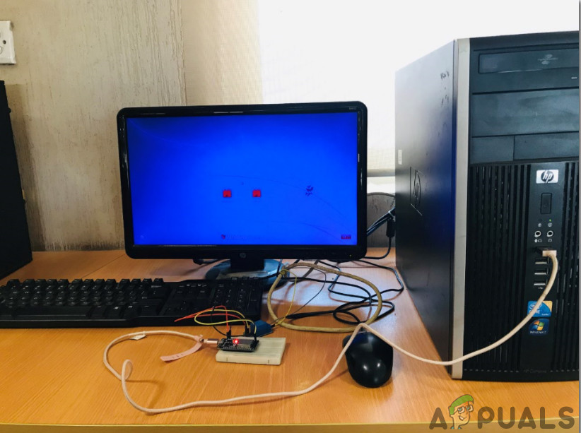
Step 8: Assembling The Circuit
Now as our app is ready and fully functional, let’s see how we will connect the circuit to the computer.
- First of all, take a switchboard and connect all the plugs of the Computer system in it i.e. Monitor, printer, CPU, PSU, etc.
- Now take the connecting switch of this board and make a cut in between of the wire so that two wires, black and red, are visible from inside.
- Take the red wire out and cut it from the middle. Connect one end of the wire in the NO point of the relay module and the other end in the COM point of the relay point. (don’t do anything with the black wire)
- Now fix the ESP32 in the breadboard and power it bu using a 5V battery. Connect the Vcc and ground of the Relay module in the breadboard, with the positive and negative terminals of the battery.
- Make the following configuration with the transistor on the breadboard.
Step 9: Code
The code is pretty simple, but still, it is briefly explained below.
1. At the start, two libraries are included so that firebase can be used with ESP32.
#include<WiFi.h>
#include <IOXhop_FirebaseESP32.h>
2. Then Information about your firebase database and the Wifi connection is given and pin of ESP is declared that will be used with the relay module.
#define FIREBASE_HOST "xxxxx" // replace it with your firebase host
#define FIREBASE_AUTH "xxxxx" // replace it with your firebase auth
#define WIFI_SSID "xxxxx"     // replace this with your WIFI SSID
#define WIFI_PASSWORD "xxxxx" // replace it with your wifi password

int swi = 34;  // connect pin34 of ESP with relay module
3. void setup() is a function that runs only one time when the circuit is powered on or the Enable button is pressed. Here the code is written t connect the ESP board to the WIFI. The pin of the ESP that is used with the relay module is also declared as OUTPUT here.
void setup() {
Serial.begin(115200);
pinMode(swi,OUTPUT);

// connect to wifi.
WiFi.begin(WIFI_SSID, WIFI_PASSWORD);
Serial.println("connecting");
while (WiFi.status() != WL_CONNECTED) {
Serial.print(".");
delay(500);
}
Serial.println();
Serial.print("connected: ");
Serial.println(WiFi.localIP());
Firebase.begin(FIREBASE_HOST, FIREBASE_AUTH);
}
4. void loop() is a function that runs repeatedly in a loop. Here, the value from the firebase is read. If this value is equal to “1”, then the HIGH signal will be sent to the relay module and the computer will switch on. When this value s “0”, the computer will be switched off.
void loop() {

// read value
if(Firebase.getFloat("switch") == 1)
{
digitalWrite(swi,HIGH);
}
else
{
digitalWrite(swi,LOW);
}

// handle error
if (Firebase.failed()) {
Serial.print("setting /number failed:");
Serial.println(Firebase.error());
return;
}
delay(1000);
} 


It is worth noting that this is highly illegal in some countries (Australia for instance) and will likely render your home insurance null and void.