How To Make Smart Home Automation System Using ESP32 Module?
In this modern era, the concept of home automation is growing at great speed. Smart systems are being installed in almost every place. Smart Home Systems is a concept in which all the electrical appliances or the devices are controlled using a single remote control. In these systems, most of the time, the remote control is a mobile application. As an android mobile is the most common among the people, so an android application is the best option to control all these devices.
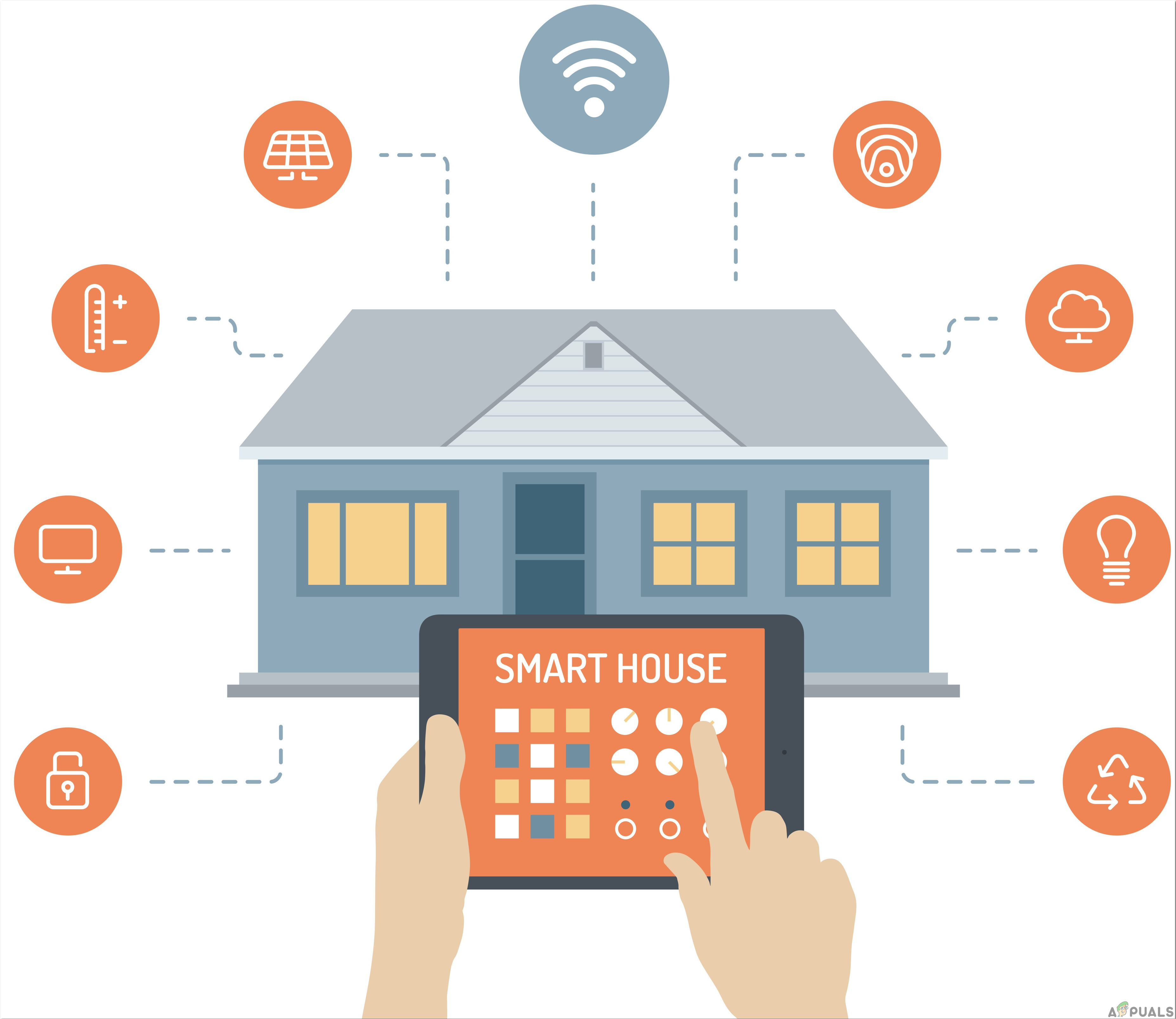
So in this project, we are going to connect some of the home’s electrical appliances to the Relay module and control it through ESP32 Microcontroller. We will make a firebase realtime database and connect it from the android app. This android app will send the data to the cloud and then it will be sent to the microcontroller to switch the electrical appliance on or off. The best part is that you can have full control over the switching of your appliances from anywhere in the world. You just need an internet connection to operate the android application.
How To Control Home Appliances Through WiFi?
Home Automation systems that are already available in the market, are very costly. We can use an ESP32 board to connect different home appliances and control them using an Android App. This will be very low in cost and an efficient way to automate the house. Now let us move a step ahead and start collecting information to start the project.
Step 1: Collecting The Components
The best approach to start any project is to make a list of components and going through a brief study of these components because no one will want to stick in the middle of a project just because of a missing component. A list of components that we are going to use in this project is given below:
- ESP32
- No products found.
- Breadboard
- Connecting Wires
Step 2: Studying The Components
Now as we know the abstract of this project, let us move one step ahead and go through a brief study of the working of the main components that we are going to use.
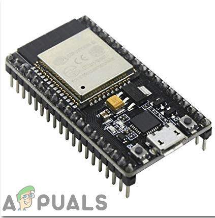
ESP32 is a low-power and low-cost microcontroller board which has a built-in WiFi and a dual-mode Bluetooth module. This Microcontroller board is created and developed by Espressif Systems. This board has built-in power amplifiers, low nice receive amplifiers, filters, and antenna switches. It is powered by an android data cable and can provide up to 3.3V on the output. ESP32 executes TCP/IP, full 802.11 b/g/n/e/I WLAN MAC convention, and Wi-Fi Direct particular. This implies ESP 32 can address a large portion of the WiFi Routers out there when utilized in station(client) mode. Likewise, it can make an Access point with full 802.11 b/g/n/e/I. ESP32 does not simply underpin the most recent BLE Bluetooth 4.2, it additionally bolsters great Bluetooth. It fundamentally implies it can address old and new Bluetooth telephones/tables. If you don’t have an ESP32 module, you can also use ESP8266 or a Node MCU. These boards can be used to perform the same task if they are connected to WiFi.
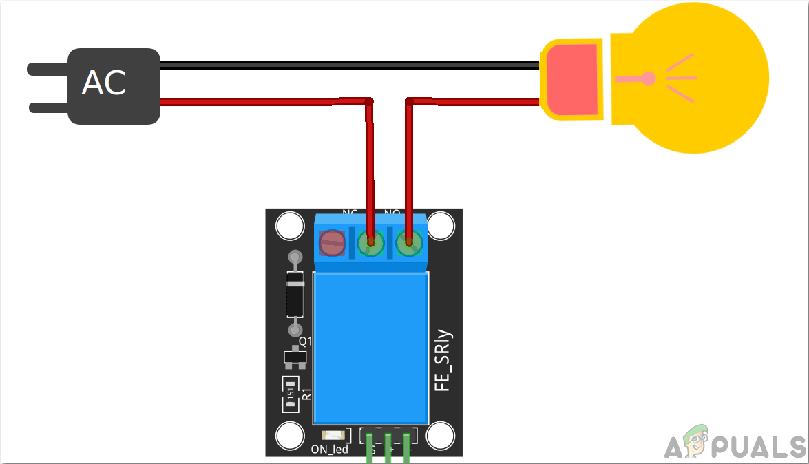
A relay module is a switching device. It works in two modes, Normally Open (NO) and Normally Closed (NC). In NO mode, the circuit is always broken unless you send a HIGH signal to the relay through Arduino. NC mode wors the other way around, The circuit is always complete unless you switch on the relay module. Make sure you connect the positive wire of your Electrical Appliance to the relay module in the way shown below.
Step 3: Block Diagram
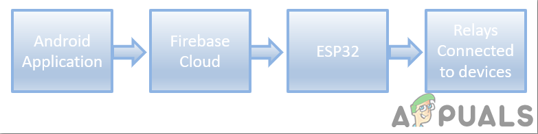
In the above block diagram, the flow of this project is shown. The relays are connected to the home’s electrical appliances or devices. A mobile application will send an On or OFF command to the database. This cloud is connected to the ESP32 microcontroller board through WiFi. To Switch the electronic device on, we will send a “1” in the database and to switch it off we will send a “0” in the database. This command will then be fetched by the microcontroller because it is also connected to the database. Based on this 0 or 1, the microcontroller will switch the relay module on or off which will ultimately result in the switching of the electrical appliances.
So here, in this article, I will use two relay modules to show you the whole procedure. But You can increase the number of relays and add the same chunk of code in your program if you want to control a bigger number of electrical home appliances.
Step 4: Assembling The Components
Now as we have a clear vision of what we want to do in this project, let us not waste any more time and start assembling the components.
- Take a breadboard and fix the ESP32 microcontroller in it. Now take the two relay modules and connect the Vcc and ground of the modules to the Vin and ground of the ESP32 microcontroller board in parallel. Connect the in-pin of the relay modules to the pin34 and pin35 of the ESP32 board. You will see that the relays are now powered on.
- Connect the home appliances to the relay module. Make sure your connections match the connections shown in the figure in Step 2.
Now as we connected the hardware part of our system. We will develop an android application that will be connected to the firebase database. We will make the database and the android application in Part 2 of this article.
Step 5: Getting Started With ESP32
If you haven’t worked on Arduino IDE before, don’t worry because a step by step to set up Arduino IDE is shown below.
- Download the latest version of Arduino IDE from Arduino.
- Connect your Arduino board to the PC and open Control Panel. Click on Hardware and Sound. Now open Devices and Printer and find the port to which your board is connected. In my case it is COM14 but it is different in different computers.
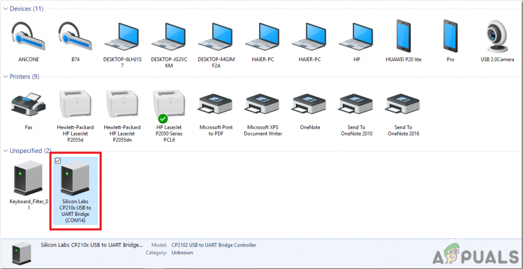
Finding Port - Click on File and then click on Preferences. Copy the following link in the Additional Board Manager’s URL. “https://dl.espressif.com/dl/package_esp32_index.json”
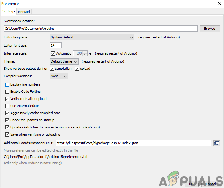
Preferences - Now, to use ESP32 with Arduino IDE, we need to import special libraries that will allow us to burn code on ESP32 and use it. these two libraries are attached in the link given below. To include the library, goto Sketch > Include Library > Add ZIP Library. A box will appear. Find the ZIP folder on your computer and click OK to include the folders.
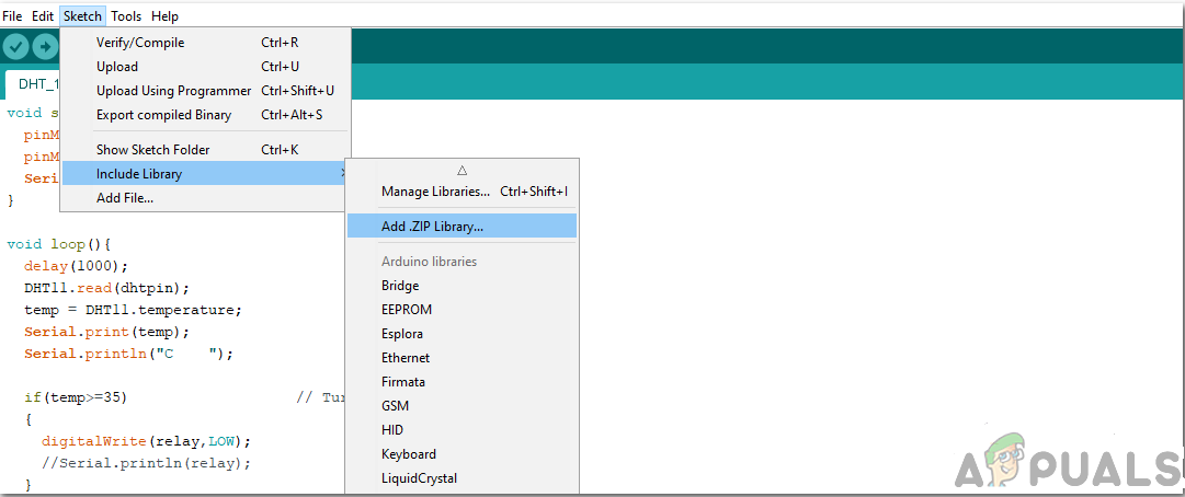
Include Library - Now goto Sketch > Include Library > Manage Libraries.
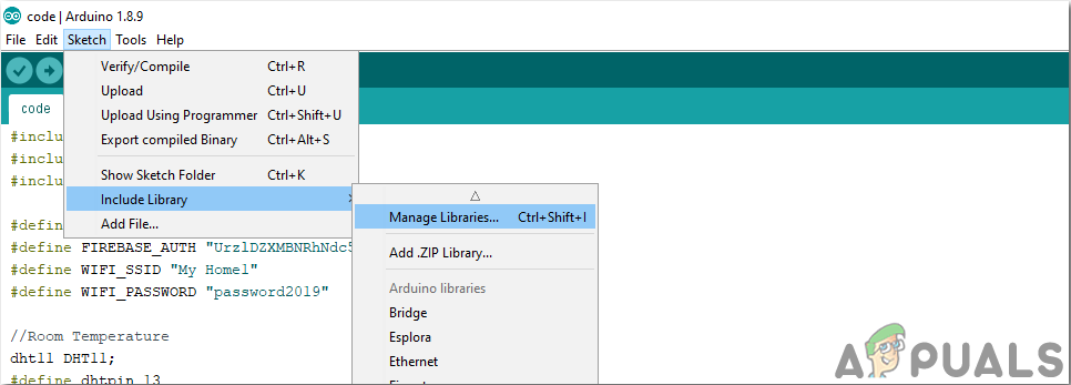
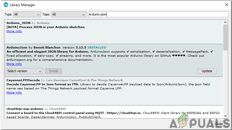
Manage Libraries - A Menu will open. In the search bar, type Arduino JSON. A list will appear. Install Arduino JSON by Benoit Blanchon.
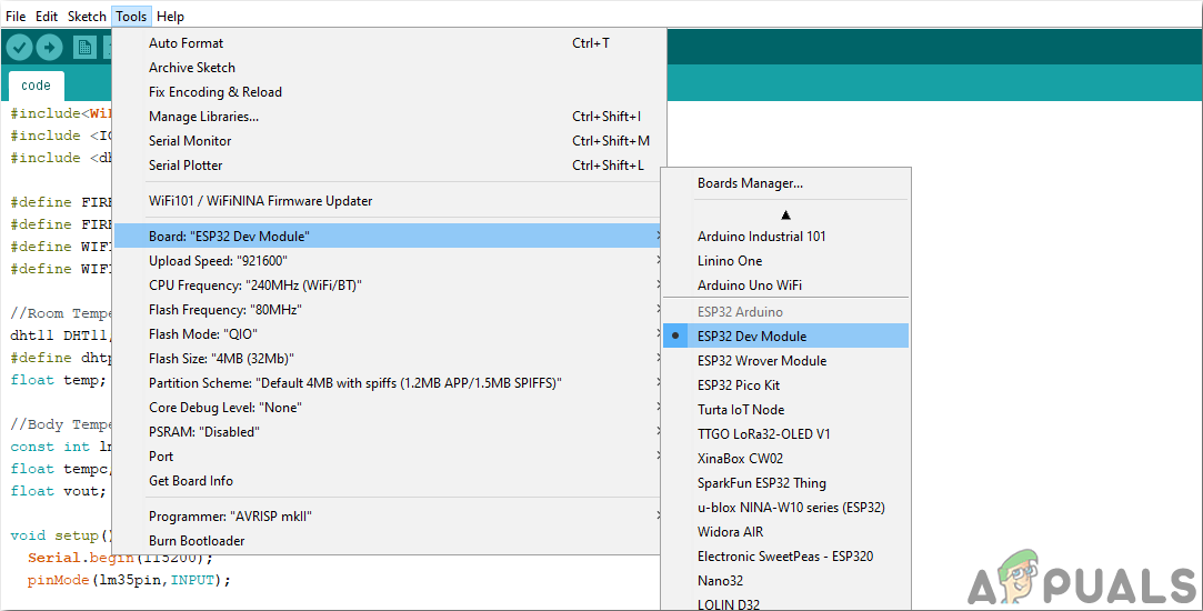
Arduino JSON - Now click on the Tools. A dropdown menu will appear. Set the board to ESP Dev Module.
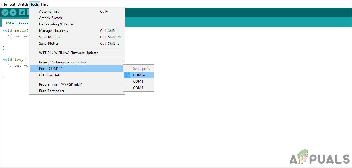
Setting Board - Click on the Tool menu again and set the port that you observed in the control panel before.
Setting Port - Now Upload the code that is attached in the link below and click on the upload button to burn the code on the ESP32 microcontroller.
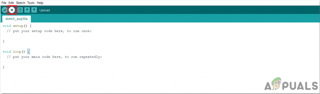
Upload
So now when you will upload the code, an error may occur. This is the most common error that may occur if you are using a new version of the Arduino IDE and the Arduino JSON. The following are the errors that you may see on the screen.
There is nothing to worry about because we can eliminate these errors by following some simple steps. These errors are arising because the new version of Arduino JSON has another class instead of StaticJsonBuffer. This is the class of JSON 5. So we can simply eliminate this error by downgrading the version of Arduino JSON of our Arduino IDE. Simply go to Sketch > Include Library > Manage Libraries. Search for Arduino JSON by Benoit Blanchon that you have installed before. Uninstall it first and then set its version to 5.13.5. Now as we have set an old version of Arduino JSON, install it again and recompile the code. This time, your code will compile successfully.
To download the code, click here.
Step 6: Understanding The Code
The code of this project is very simple and well commented. But still, the code is briefly explained below.
1. In the start, libraries are included so that the ESP32 board can be connected to the local WiFi connection in the home or office. After this, a link to your firebase project and the authentication of your firebase project are defined. Then the name and password of your local wifi connection are defined so that the ESP32 could be connected to the Wifi. Some pins of ESP32 are defined to be connected to the relay modules. and at last a variable is declared that will store some temporary data that will come from the firebase cloud.
#include<WiFi.h>                   // include library to connect to the local Wifi connection
#include <IOXhop_FirebaseESP32.h>  // Include library to connect to Firebase databse

#define FIREBASE_HOST "coma-patient.firebaseio.com"              // link of your firebase project
#define FIREBASE_AUTH "UrzlDZXMBNRhNdc5i73DRW10KFEuw8ZPEAN9lmdf" // authentication of your firebase project
#define WIFI_SSID "abcd"                                         // name of the WiFi connection
#define WIFI_PASSWORD "abcd"                                     // password of the WiFi connection

int r1 = 34;   // pin to connect relay 1
int r2 = 35;   // pin to connect relay 2
int temp;      // variabe to carry data
2. void setup() is a function in which we initialize the INPUT or OUTPUT pins. This function also sets the baud rate by using Serial.begin() command. Baud Rate is the communication speed of the microcontroller. Some lines of code are added here to connect the ESP32 to the local wifi connection. The board will try to connect to the local wifi connection and will print “connection.” in the serial monitor. It will print “Connected” when the connection is established. So to monitor this, it is better to open the serial monitor and check its staus there.
void setup() {
 Serial.begin(115200);                     // setting the baud rate

                                          // connect to wifi.
 WiFi.begin(WIFI_SSID, WIFI_PASSWORD);
 Serial.println("connecting");
 while (WiFi.status() != WL_CONNECTED) {
  Serial.print(".");
  delay(500);
 }
 Serial.println();
 Serial.print("connected: ");
 Serial.println(WiFi.localIP());
 Firebase.begin(FIREBASE_HOST, FIREBASE_AUTH);
}
3. void loop() is a function which runs repeatedly in a loop. In this loop, we write a code that tells the microcontroller board what tasks to carry out and how. We have fetched the data against light and AC from the database and stored in the two temporary variables. Then four conditions are applied to switch the two appliances according to the fetched 0 or 1 from the database.
void loop() {
 // get value
 temp1 = Serial.println(Firebase.getFloat("light"));    // get the value for the switcching of the light
 temp2 = Serial.println(Firebase.getFloat("AC"));      // get the vaue for the switching of Fan
 delay(1000);
 if (temp1 == 1 && temp2 == 1){                         // To turn on light and fan
  digitalWrite(r1,HIGH);
  digitalWrite(r2,HIGH);
 }
 if (temp1 == 0 && temp2 == 1){                          // To turn on fan and turn off light
  digitalWrite(r1,LOW);
  digitalWrite(r2,HIGH);
 }
 if (temp1 == 1 && temp2 == 0){                          // To turn off fan and turn on light
  digitalWrite(r1,HIGH);
  digitalWrite(r2,LOW);
 }
 if (temp1 == 0 && temp2 == 0){                           // To turn off fan and turn off light
  digitalWrite(r1,LOW);
  digitalWrite(r2,LOW);
 }
}
This was Part one of the “How To Make Smart Home System Using ESP32?”. You can add more relay modules if you want to control some more home appliances, the only thing that you will need to do is to read data from the firebase and add some more conditions for the switching. In the next article, I will explain how to develop an android application and Firebase database. I will explain the step by step procedure to connect the android app to the firebase and send data to it.
To go to the next tutorial Click Here


Hello, I have problems to receive the information to the NODEMCU card, from the app to the firebase database the information arrives, but from firebase to the card they do not arrive, if I want to activate a Relay I have to do it directly from the database since the information does not arrive