What is Spanning Tree Protocol (STP) and how it works?
In a networking infrastructure, a loop occurs when network packets continuously circulate among two or more network devices without reaching their intended destination. This situation arises due to redundant or multiple paths between network devices, causing packets to travel in a loop indefinitely.
Network loops can severely disrupt network performance, leading to slow or unresponsive networks, increased congestion, and even network crashes. Preventing network loops is critical to maintaining a stable and efficient network.
Network loops can occur due to various reasons, here are a few examples.
- Redundant connections: Redundant connections between network devices, such as switches or routers, can cause network loops by allowing packets to travel through multiple paths, leading to congestion and loop formation.
- Misconfigured network devices: Misconfigured network devices can cause network loops. For example, if two switch ports are incorrectly configured to be in the same VLAN, packets may be forwarded between them, creating a loop.
- Network design issues: Poor network design can contribute to network loops. Adding redundant links to a network that is not appropriately designed for redundancy may result in network loops.
- Human error: Human error can also cause network loops by making mistakes during the configuration or alteration of network devices or cables.
Let’s explore how to prevent network loops and overcome related issues in a network.
Spanning Tree Protocol (STP)
Spanning Tree Protocol (STP) is a widely used and effective method for preventing loops in a network. It helps prevent loops by actively monitoring the network topology and selectively blocking redundant links. This ensures that there is only one active path between any two network devices. By doing so, STP helps prevent broadcast storms and network congestion that can result from loops. Although there are other methods to prevent network loops, STP is a robust and reliable solution. It is supported by most network devices and is widely implemented in enterprise networks.
How does STP work?
STP determines which interfaces should forward traffic, and any remaining interfaces are placed in a blocking state. STP uses three criteria to determine whether an interface should be placed in a forwarding state.
- Selecting the root bridge
- Selecting the root port
- Selecting the designated port & non designated port
1. Root Bridge Selection.
In a network with multiple switches, one switch is elected as the root bridge, which becomes the central point of the network. The root bridge is selected through an election process based on the bridge IDs of the switches in the network. The bridge ID is a unique identifier assigned to each switch and is calculated by combining a priority value and the MAC address of the switch.
When STP is first enabled on a switch, it assumes that it is the root bridge and begins broadcasting BPDU (Bridge Protocol Data Unit) messages to other switches. Each switch that receives the BPDU message compares the bridge ID of the sending switch with its own bridge ID. The switch with the lowest bridge ID is selected as the root bridge, and all other switches adjust their STP configurations accordingly.
If two switches have the same priority value, the switch with the lower MAC address is selected as the root bridge. In case of a tie, the root bridge is selected based on the port priority and port ID. Once the root bridge has been selected, the network topology is calculated, and the STP determines the best path for forwarding data across the network.
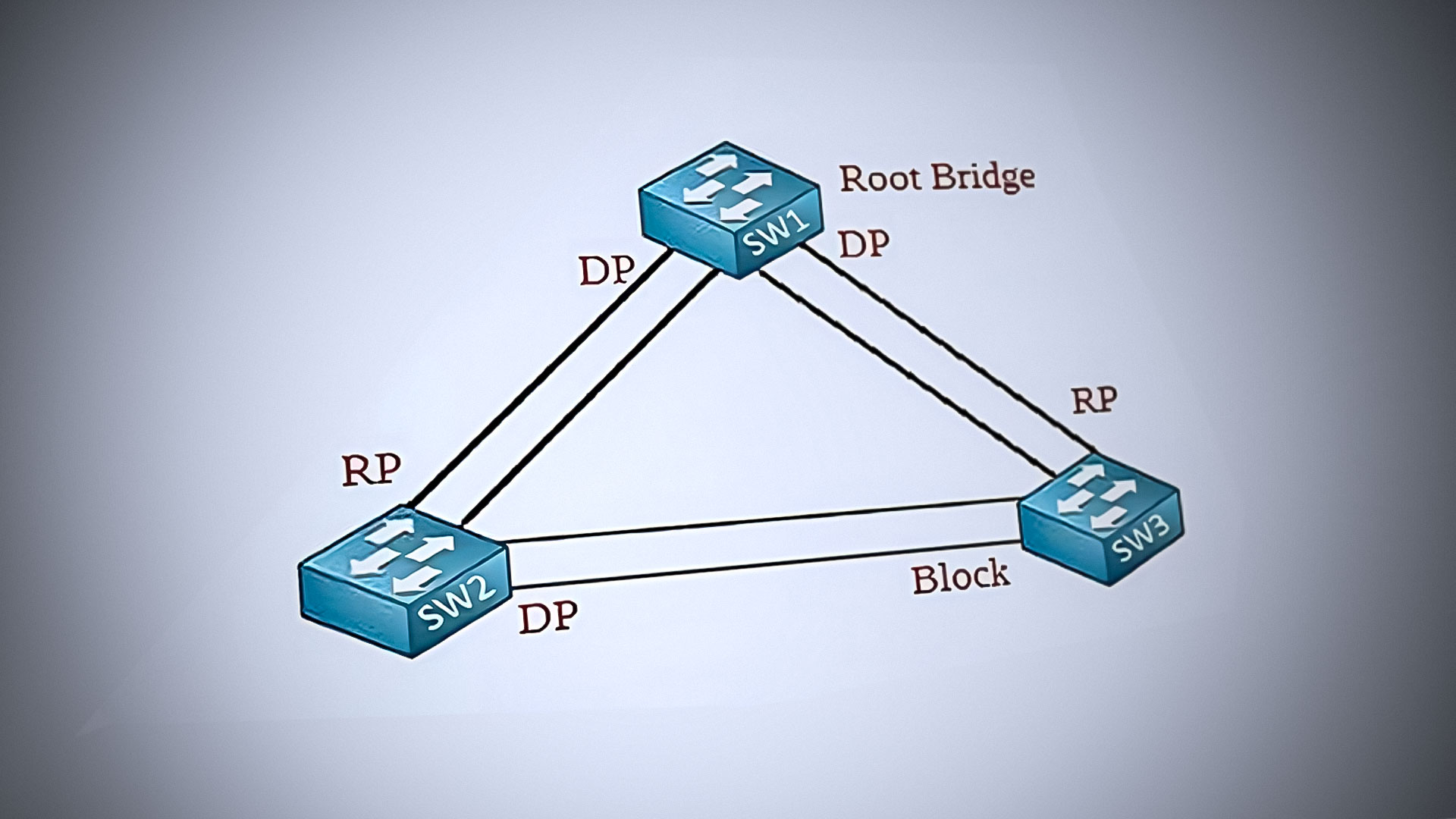
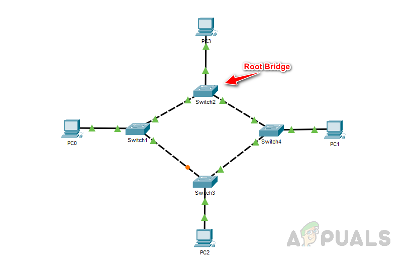
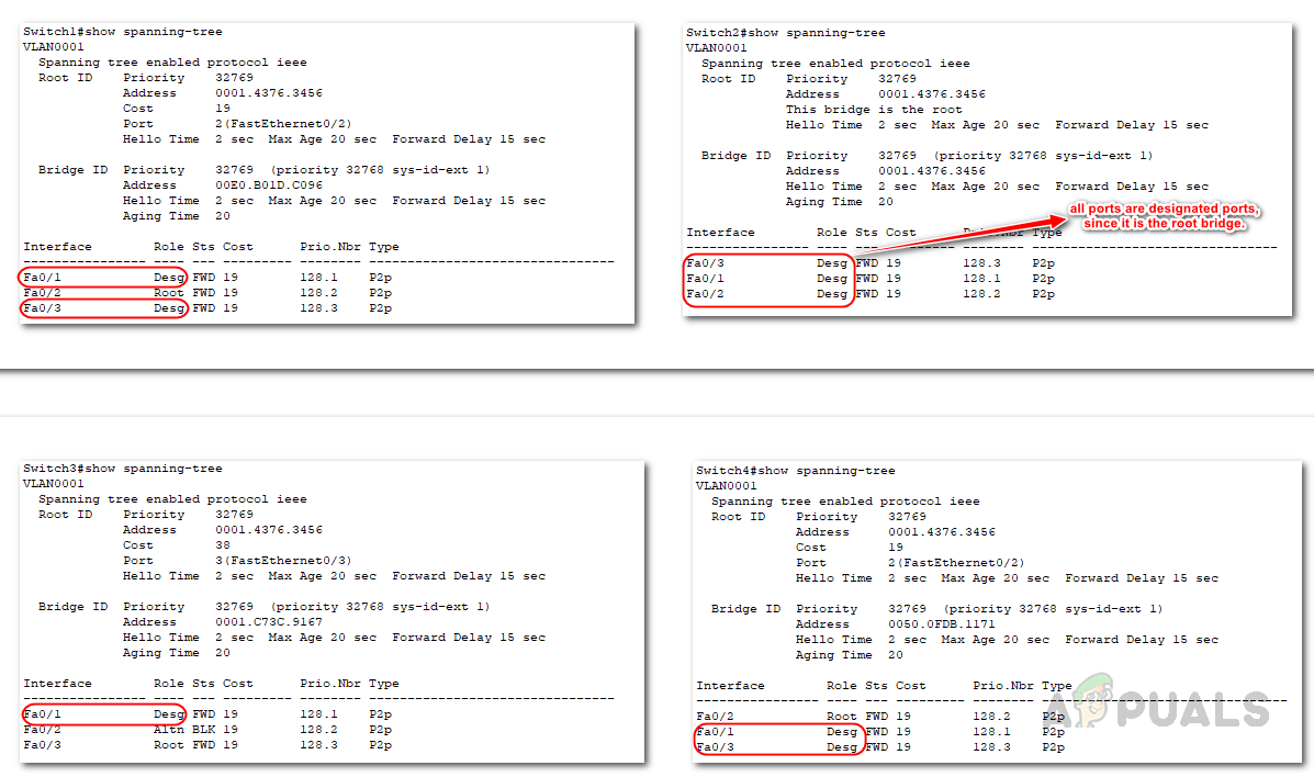
In the following example, Switch 1 has been selected as the root bridge based on its Bridge ID value. Despite all switches having the same priority value, Switch 1 has the lowest MAC address when the MAC ID is combined with the priority value; hence, it becomes the root bridge.
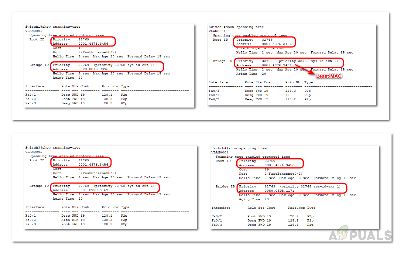
By default, switches have Spanning Tree Protocol (STP) enabled. Use the command below to verify the root bridge, root port, and designated port details.
show spanning-tree
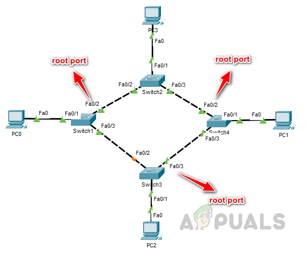
2. Root Port Selection.
Every non-root bridge determines the most efficient path to reach the root bridge. The port providing the shortest path becomes the designated root port for that non-root bridge. Each non-root bridge has only one root port, which offers the quickest path to the root bridge.
The root port is selected by comparing the cost of each non-root switch’s ports to reach the root bridge. The port with the lowest cost is chosen as the root port. The cost of a port is determined by the speed of the link between the switch and the root bridge. STP uses a metric called the Path Cost to calculate the cost of a port. The Path Cost is based on the link’s speed, with higher speeds resulting in lower Path Costs.
During the root port selection process, a tie can occur when two or more ports on a non-root bridge have the same cost to reach the root bridge. In such cases, the following tie-breaking mechanisms are used.
- The Bridge ID of the forwarding switch is compared, and the switch with the lowest Bridge ID becomes the root bridge. Its corresponding port is then selected as the root port. In this example, Switch 3 can reach the root bridge through either Switch 1 or Switch 4.
 As the cost is the same on both of Switch 3’s interfaces, the forwarding switch’s MAC ID is used as a tiebreaker. Since Switch 4 has the lowest MAC ID, port Fa0/3 is selected as the root port on Switch 3.
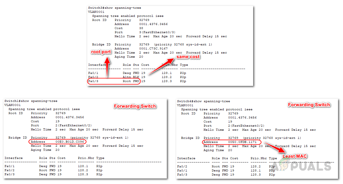
- If there is still a tie after comparing the Bridge IDs (which can happen if multiple links are connected to the same switch), the lowest neighbor port priority value is used. By default, the port priority value is 128. If there is still a tie, the forwarding switch selects the port with the lowest number as the root port. In this example, Switch 3 has multiple links to reach the root bridge, resulting in a tie in the forwarding switch’s bridge ID.
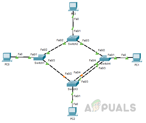
To break this tie, port priority is used as the tiebreaker. Since the port priority is also the same for these ports, the lowest port number is used as the deciding factor, resulting in the selection of port Fa0/3 as the root port.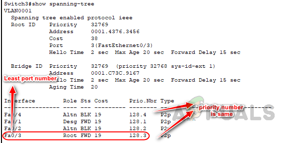
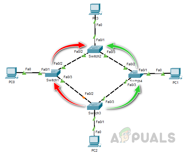
3. Selection of Designated and Non-Designated Ports
The designated ports are responsible for forwarding traffic on the network, while non-designated ports are blocked to prevent loops from occurring. Similar to the root port selection process, the designated port is determined by the lowest path cost to reach the root bridge. It is important to note that all the ports on the root bridge are designated ports.
If there is a tie in the path cost, the switch ID is compared to determine the designated port. If there is still a tie in the switch ID, the local port number is used to break the tie, and the switch with the lowest port number is designated as the designated port.
Once the designated port is selected, all other ports on the switch that are not designated ports are placed in a blocking state. This prevents loops in the network and ensures that traffic flows in the correct direction.
In conclusion, understanding the process by which STP selects the root bridge, root port, and designated as well as non-designated ports is essential for preventing network loops that can severely disrupt network performance. Network loops can cause slow or unresponsive networks, increased congestion, and even network crashes. Therefore, implementing STP — as a widely-used and effective method for preventing loops in a network — is critical to maintaining a stable and efficient network.