How To Make Arduino Based Calculator?
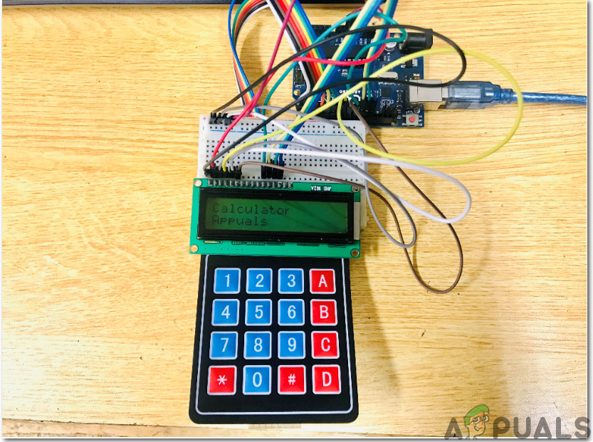
Making projects using Arduino Uno as a microcontroller board is really fun if you are working on Embedded projects. If you want to make a simple calculator that is able to perform all the basic arithmetical operations like addition, subtraction, multiplication, and division, you can make it right now if you have know-how with the Arduino board. So in this project, we are going to use an Arduino Uno to make a simple calculator. We will integrate a 4×4 Keypad to send the input and a 16×2 LCD to see the output of our operations.
So, as we now know the basic abstract of our project that what we want to achieve in the end, let us move ahead and start gathering further information so as to start working on this project.
How To Make A Simple Calculator On Arduino?
Step 1: Collecting The Components
Before starting any project, the initial step is to make a complete list of all the components that are going t be used in the project. This is a perfect approach because it saves a lot of time and prevents us from getting stuck in the middle of the project. So, a complete list of all the components that are easily available in the market, is given below:
- Arduino Uno
- No products found.
- No products found.
- No products found.
- No products found.
- No products found.
Step 2: Working
As we now have all the components that we are going to use in this project, let us start working on this project. We are going to use an Arduino Uno as the microcontroller board. A code will be written and burnt on this board which will tell the board what operations to perform and how. A 4×4 keypad will be used to input the numerical data that is to be computed in the calculator. The microcontroller will perform all the arithmetical operations and then send the output to the 16×2 LCD.
Before connecting the hardware, it is better to simulate and test the code and the circuit connections on computer software. We will use Proteus for this purpose. After testing the circuit and confirming that it is working perfectly fine on the software, we will move towards the hardware.
Step 3: Simulating the Circuit
Before implementing this project on hardware, we will simulate it on Proteus first to check if the code works fine or not. If you have not worked on Proteus before, there is nothing to worry about. To simulate the circuit on software, go through the following steps.
- If you don’t have this software installed on your computer already, click here to download it.
- After the software is installed, open the software and make a new project by click on the ISIS button.

ISIS - Proteus does not have an Arduino library initially. We will have to include it. The Arduino library for proteus is attached along with the code in the link given below. Copy the files and paste them in C:\ProgramData\Labcenter Electronics\Proteus 8 Professional\LIBRARY.
- A new schematic has just opened. Click on the P button to open the component menu.
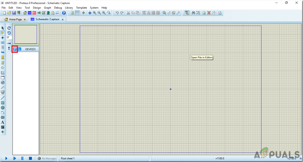
New Schematic - A box will appear containing a search bar on the top left corner. Search the component that you need to use in the project.
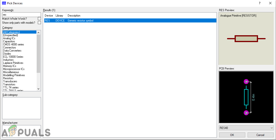
Selecting Components - After selecting all the components, you will see a complete list on the left side of the screen.
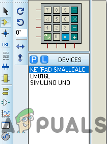
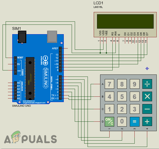
Component List - Make a circuit diagram as shown below.
Circuit Diagram - Now open the Arduino file that is given below. In the Sketch menu, click on Export Compiled Binary. This will generate a .hex file that will be used in the simulation of Arduino in Proteus.
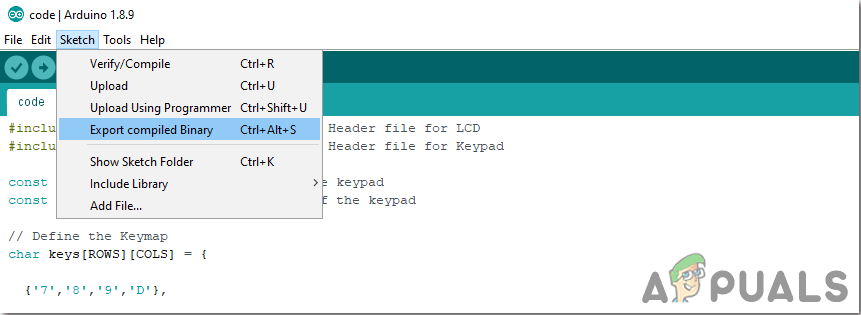
Generating HEX - These are the two files that will be generated. We will use the first one in our simulations.

HEX files - Now as the HEX file is generated, open the proteus and double click on the microcontroller board. A box will appear to edit the component. Upload the hex file there.
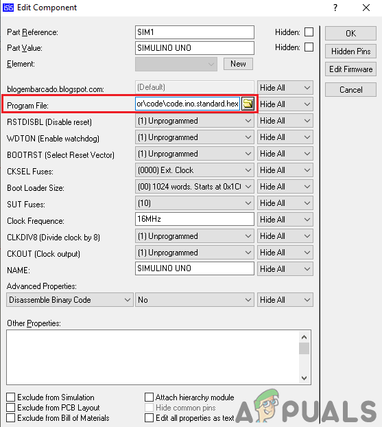
Uploading the HEX file As the code is uploaded here successfully, you can test the calculator by performing some arithmetical operation and confirm the results.
Step 4: Assembling The Circuit
As the circuit is simulated and the code works perfectly fine on it. Let us move a step ahead and assemble all the components together on the Veroboard to make a final product. Go through the following steps to make all the connections in the circuit.
- There are a total of 8 pins on the 4×4 keypad named A, B, C, D, 1, 2, 3, and 4. Make sure you connect the A, B. C and D pin to the pin0, pin1, pin2, and pin3 of the Arduino Uno board and pin 1, 2, 3, and 4 pins of the keypad to the pin4, pin5, pin6 and pin7 of the Arduino Uno board respectively.
- Now Connect the D4, D5, D6 and D7 pin of the 16×2 LCD to the pin10, pin11, pin12, and pin13 of the Arduino board respectively.
- Now connect the RE and E pin of the LCD to the pin8 and pin9 of the Arduino board respectively.
- Short the VSS, VEE and RW pin of the LCD and connect them to the ground of the Arduino Uno.
- Power up the LCD by connecting the VDD pin of the LCD to the 5V of the Arduino UNO.
Step 5: Getting Started With Arduino
Arduino IDE is a software on which you can write, debug, and compile a code that will run on an Arduino microcontroller. This code will be uploaded to the microcontroller through this IDE. IF you have no previous experience with this software, there is nothing to worry about because the whole procedure to use this software is given below.
- If you don’t have the software already installed, click here to download the software.
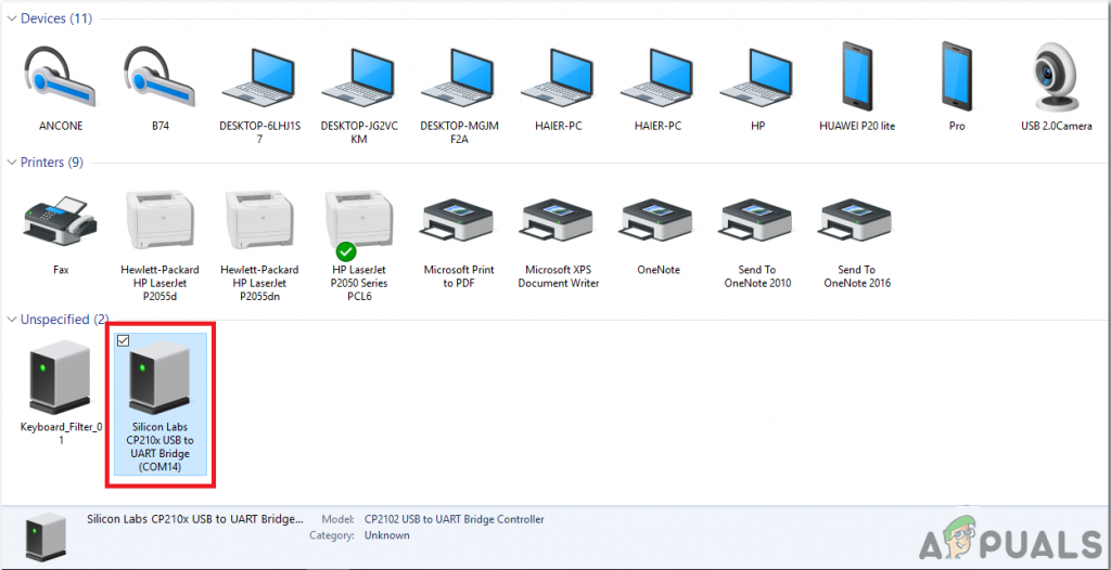
- Connect your Arduino board to the PC and open Control Panel. Click on Hardware and Sound. Now open Devices and Printer and find the port to which your board is connected. This port is different on different computers.
Finding Port - Now open the Arduino IDE. From Tools, set the Arduino board to Arduino / Genuino UNO.

Setting Board - From the same Tool menu, set the port number. This port number should be exactly the same as the port number that was observed before in the control panel.
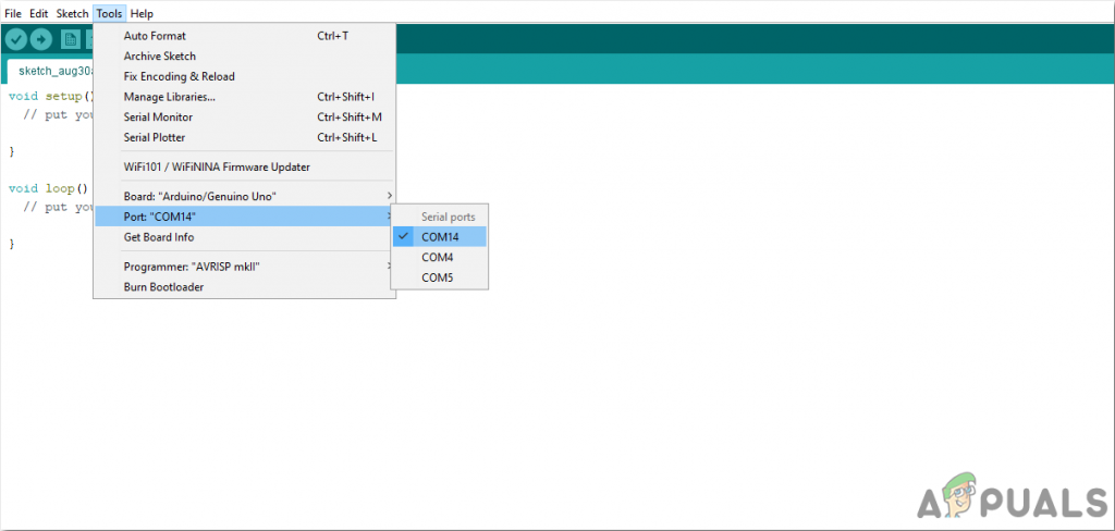
Setting Port - Now, to use 4×4 keypad and the 16×2 LCD with Arduino IDE, we need to import special libraries that will allow us to burn code on Arduino Uno and use it. these two libraries are attached in the link given below. To include the library, goto Sketch > Include Library > Add ZIP Library. A box will appear. Find the ZIP folder on your computer and click OK to include the folders. This library is attached along with the code in the link below.
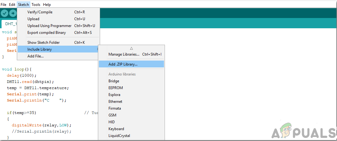
Include Library - Download the code attached below and copy it to your IDE. To upload the code, click on the upload button.
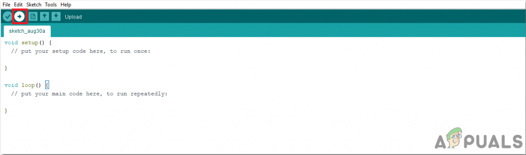
Upload
To download the code, click here.
Step 6: Understanding The Code
The code is very well commented. But still, for your ease, it is explained below.
1. At the start, the header files are written to include the libraries so that the keypad and LCD can be interfaced with the Arduino Uno board.
#include <LiquidCrystal.h> // Include Header file for LCD
#include <Keypad.h> // Include Header file for Keypad
2. After that, two variables are declared to hold the number of rows and columns of the keypad. The keymap tels us about the sequence of keys present in the keypad.
const byte ROWS = 4; // Four rows of the keypad
const byte COLS = 4; // Three columns of the keypad

// Define the Keymap
char keys[ROWS][COLS] = {
{'7','8','9','D'},
{'4','5','6','C'},
{'1','2','3','B'},
{'*','0','#','A'}
};
3. After that, it is specified which row and column of the keypad are connected to which pin of the Arduino. After it is all done, a keypad can be created by mapping all of its pins.
// Connect keypad ROW0, ROW1, ROW2 and ROW3 to these Arduino pins 0,1,2,3 respectively.
byte rowPins[ROWS] = { 0, 1, 2, 3 };
// Connect keypad COL0, COL1 and COL2 to these Arduino pins 4,5,67 respectively.
byte colPins[COLS] = { 4, 5, 6, 7 };

Keypad kpd = Keypad( makeKeymap(keys), rowPins, colPins, ROWS, COLS ); //  Create the Keypad
4. After that, we tell that which pins of the LCD are connected to which pins of the Arduino.
const int rs = 8, en = 9, d4 = 10, d5 = 11, d6 = 12, d7 = 13; // Pins to which LCD is connected
LiquidCrystal lcd(rs, en, d4, d5, d6, d7);                    // Create the LCD
5. Then some variables are initialized to hold the values of calculations and perform operations during the run time.
long Num1,Num2,Number;
char key,action;
boolean result = false;
6. void setup() is a function that runs only once when the circuit is powered on. In this function, we declare which pin of the Arduino board will be used to take the input and which will be used to send the output. Baud rate is also set in this function which is basically the speed of communication in bits per second.
void setup() {
Serial.begin(9600);
lcd.begin(16, 2);                //We are using a 16*2 LCD display
lcd.print("Calculator");         //Display a intro message
lcd.setCursor(0, 1);             // set the cursor to column 0, line 1

delay(1000);                     //Wait for 1 second
lcd.clear();                     //clear the LCD screen
}
7. CalculateResult() is a function that will be used to detect the sign pressed on the keypad. on the basis of sign pressed, it will decide which arithmetical operation to perform.
void CalculateResult()
{
if (action=='+')      // if + sign is pressed
Number = Num1+Num2;   // add both numbers

if (action=='-')      // if - sign is pressed
Number = Num1-Num2;   // subtract both numbers

if (action=='*')      // if * sign is pressed
Number = Num1*Num2;   //multiply both numbers

if (action=='/')      // if / sign is pressed
Number = Num1/Num2;   // divide both numbers
}
8. DisplayResult() is a function that is used to display the result on the LCD. First of all, it sets the cursor to the initial position and prints the first number. Then it displays the logical operator and then the second number. Then after printing the “=” sign, it will display the answer on the LCD.
void DisplayResult()
{
lcd.setCursor(0, 0);     // set the cursor to column 0, line 1
lcd.print(Num1);         // print the first number on the screen
lcd.print(action);       // print the sign pressed on the screen
lcd.print(Num2);         // print the second number on the screen

if (result==true)        //Display the result
{
lcd.print(" = ");        // print the = sign on the screen
lcd.print(Number);       // print the answer on the screen
}
}
9. DetectButtons() is a function that is used to detect which button is pressed. it will also detect if the button is pressed twice. This function will return a number that will be pressed on the keypad.
void DetectButtons()
{
 lcd.clear();                       //Then clean it
 if (key=='*')                      //If cancel Button is pressed
 {
  Serial.println ("Button Cancel"); // print a comment
  Number=Num1=Num2=0;
  result=false;
 }

 if (key == '1')                     //If Button 1 is pressed
 {
  Serial.println ("Button 1");
  if (Number==0)
   Number=1;
  else
   Number = (Number*10) + 1;         //Pressed twice
 }

 if (key == '4')                     //If Button 4 is pressed
 {
  Serial.println ("Button 4");
  if (Number==0)
   Number=4;
  else
   Number = (Number*10) + 4;         //Pressed twice
 }

 if (key == '7')                     //If Button 7 is pressed
 {
  Serial.println ("Button 7");
  if (Number==0)
   Number=7;
  else
   Number = (Number*10) + 7;         //Pressed twice
 }

 if (key == '0')                     //If Button 0 is pressed
 {
  Serial.println ("Button 0");
  if (Number==0)
   Number=0;
  else
   Number = (Number*10) + 0;         //Pressed twice
 }

 if (key == '2')                     //Button 2 is Pressed
 {
  Serial.println ("Button 2");
  if (Number==0)
   Number=2;
  else
   Number = (Number*10) + 2;         //Pressed twice
 }

 if (key == '5')                     //Button 5 is Pressed
 {
  Serial.println ("Button 5");
  if (Number==0)
   Number=5;
  else
   Number = (Number*10) + 5;         //Pressed twice
 }

 if (key == '8')                     //Button 8 is Pressed
 {
  Serial.println ("Button 8");
  if (Number==0)
   Number=8;
  else
   Number = (Number*10) + 8;         //Pressed twice
 }

 if (key == '#')                     //Button # is Pressed
 {
 Serial.println ("Button Equal");
 Num2=Number;
 result = true;
 }

 if (key == '3')                     //Button 3 is Pressed
 {
  Serial.println ("Button 3");
  if (Number==0)
   Number=3;
  else
   Number = (Number*10) + 3;         //Pressed twice
 }

 if (key == '6')                     //Button 6 is Pressed
 {
  Serial.println ("Button 6");
  if (Number==0)
   Number=6;
  else
   Number = (Number*10) + 6;         //Pressed twice
 }

 if (key == '9')                     //Button 09 is Pressed
 {
  Serial.println ("Button 9");
  if (Number==0)
   Number=9;
  else
   Number = (Number*10) + 9;         //Pressed twice
 }

 if (key == 'A' || key == 'B' || key == 'C' || key == 'D')  //Detecting Buttons on Column 4
 {
  Num1 = Number;
  Number =0;
  if (key == 'A')
  {
   Serial.println ("Addition");
   action = '+';
  }
  if (key == 'B')
  {
   Serial.println ("Subtraction");
   action = '-';
  }
  if (key == 'C')
  {
   Serial.println ("Multiplication");
   action = '*';
  }
  if (key == 'D')
  {
   Serial.println ("Devesion");
   action = '/';
  }

  delay(100);
 }
}
10. void loop() is a function that will run again and again in a loop. This function is used to call all the other functions that will be used to perform all the operations. Those functions are explained above.
void loop() {

key = kpd.getKey();  //storing pressed key value in a char

if (key!=NO_KEY)
DetectButtons();     // call function

if (result==true)
CalculateResult();   // call function

DisplayResult();     // call function
}
Step 7: Testing
Now as we have connected all the components together and uploaded the code in the microcontroller, let’s test the calculator if it works fine or not. To test the calculator, press any numeric key. After that press A and then again press any numeric key. When you have done this, the LCD will display the addition of both the numbers.
This was the whole procedure to make and test a calculator using Arduino. Now you can enjoy making your own Arduino based calculator at home.


