How To Design A Battery Level Indicator circuit?
In the recent century, everything that is used in day to day life is electronic. Most of the electronic components that are small scale use a battery to power themselves up. Sometimes these electronic devices, such as toys, shavers, music players, car batteries etc, don’t have a display to indicate the level of the battery. So to check the level of their battery, we need a device that will indicate the level of the battery and tell us that if the battery is to be changed immediately or after some time. Different battery level indicators are available in the market. But if we want this device in low-cost, we can make it at home that will be as efficient as the device available in the market. 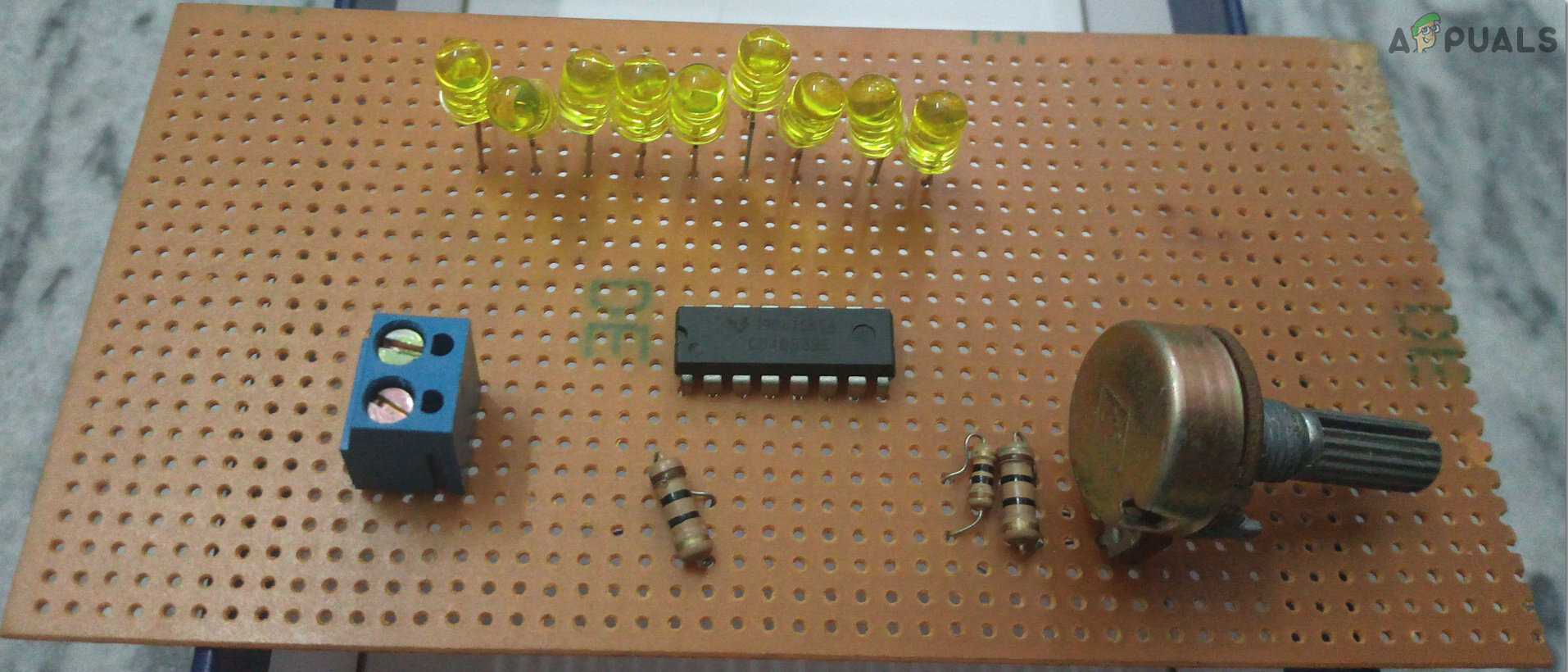
In this Project, I will tell you the best way to plan a simple Battery Level Indicator Circuit utilizing effectively accessible segments, from the market. The battery level indicator demonstrates the status of the battery just by switching on LEDs. For instance, five LEDs are turned on means that the battery limit is 50%. This circuit will be fully based on LM914 IC.
How to indicate battery level using LM3914 IC?
This article clarifies to you how to plan the battery level indicator. You can utilize this circuit to check vehicle battery or inverter. So by utilizing this circuit, we can expand the lifetime of the battery. Let us gather some more information and start working on this project.
Step 1: Collecting The Components
The best approach to start any project is to make a list of components and going through a brief study of these components because no one will want to stick in the middle of a project just because of a missing component. A list of components that we are going to use in this project is given below:
- No products found.
- No products found.
- No products found.
- No products found.
- No products found.
- 56KΩ Resistor
- 18KΩ Resistor
- 4.7KΩ Resistor
- No products found.
- Connecting wires
- No products found.
Step 2: Studying The Components
Now as we know the abstract of our project and we also have a complete list of all the components, let us move a step ahead and go through a brief study of the components we are going to use.
LM3914 is an integrated circuit. Its job is to operate the displays who visually show the change in an analog signal. On its output, we can connect up to 10 LEDs, LCDs, or any other fluorescent display component. This Integrated Circuit is usable just because of the linear scaling threshold is linearly scaled. In the fundamental arrangement, it gives a ten-stage scale which is expandable to more than 100 portions with other LM3914 ICs in series. In 1980, this IC was developed by National Semiconductors. But now in 2019, it is still available as Texas Instruments. There are two main variants of this IC. one is LM3915, which has a 3dB logarithmic scale step and the other is LM3916, which operates the scale of a Standard Volume Indicator (SVI). The operating voltage range varies from 5V to 35V and it can drive LED displays on its output by providing a regulated output current that ranges from 2-30mA. The internal network of this IC consist of ten comparators and a resistor scaling network. Each comparator turns on one by one when the input voltage level increases. This IC can be set to operate in two different modes, a Bar Graph Mode and a Dot Mode. In bar graph mode, all the lower-output terminals switch on and in a dot mode, only one output switches on at a time. The device has a total of 18 pins. 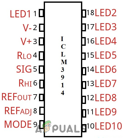
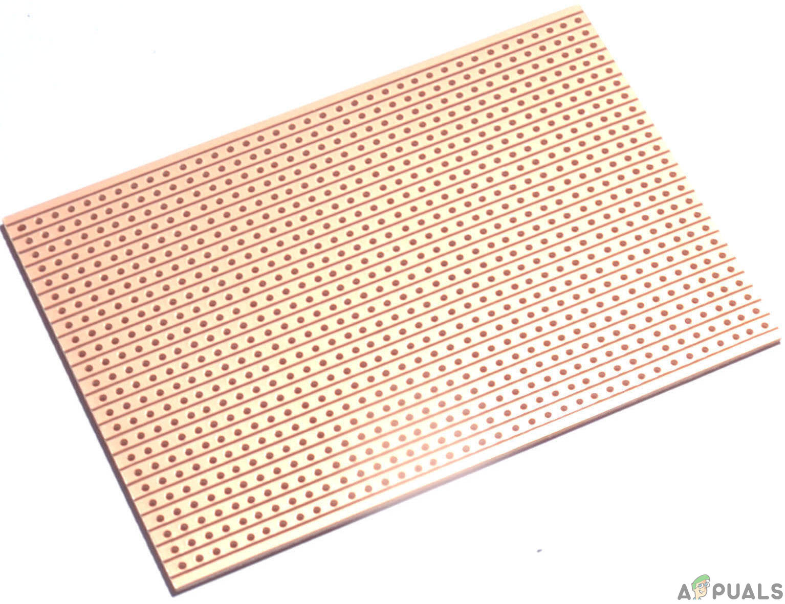
Veroboard is an excellent choice to make a circuit because the only headache is to place components on Vero-board and solder them and check the continuity using the Digital Multi Meter. Once the circuit layout is known, cut the board into a reasonable size. For this purpose place the board on the cutting mat and by utilizing a sharp blade (securely) and by taking all the safety precautions, more than once score the load up top and base along the straight edge (5 or multiple times), running over the apertures. After doing so, place the components on the board closely to form a compact circuit and solder the pins according to the circuit connections. In case of any mistake, try to de-solder the connections and solder them again. Finally, check the continuity. Go through the following steps to make a good circuit on a Veroboard.
Step 3: Circuit Design
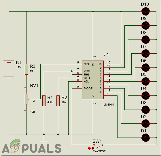
The core of this battery level marker circuit is LM3914 IC. This IC takes analog voltage as input and drives 10 LED’s directly as per the level of alternating voltage. In this circuit, there is no need for resistors in arrangement with LEDs because the current is directed by the IC itself.
In this circuit LED’s (D1-D10) shows the limit of the battery in either dot mode or display mode. This mode is chosen by the outer switch sw1 which is associated with the ninth pin of IC. sixth and seventh pins of IC are associated with the ground through a resistor. The brightness of the LEDs is controlled by this resistor. Here resistor R3 and POT RV1 structures potential divider circuit. Here in this circuit, calibration is done by setting the knob of the potentiometer. There is no need for any outer power supply to this circuit.
The circuit is intended to monitor 10V to 15V DC. The circuit will work regardless of whether the battery voltage is 3V. Lm3914 drives led’s, LCDs and vacuum fluorescents. The IC contains flexible reference and precise 10-steps divider. This IC can likewise go about as a sequencer.
To indicate the status of the output, we can connect LEDs of different colors. Connect red LEDs from D1 to D3 which demonstrates shut down phase of your battery and use D8-D10 with green LED’s which shows 80 to 100 level of the battery and utilize yellow LEDs for remaining.
With a little adjustment, we can utilize this circuit to quantify voltage ranges too. For this disconnect, the resistor R2 and interface upper voltage level to the input. Now, shift the opposition of Pot RV1 to the D10 LED gleams. Presently evacuate upper voltage level at the input and associate lower voltage level with it. Interface a high valued variable resistor in the spot of resistor R2 and fluctuate it till the D1 LED shines. Now disconnect the potentiometer and measure the resistance across it. Now connect the resistor of the same value in place of R2. The circuit will now measure different voltage ranges.
This circuit is most reasonable for indicating 12V of the battery level. In this circuit, each LED demonstrates 10 percent of the battery.
Step 4: Simulating The Circuit
Before making the circuit it is better to simulate and examine all the readings on a software. The software we are going to use is the Proteus Design Suite. Proteus is a software on which electronic circuits are simulated.
Proteus 8 Professional can be downloaded from Here
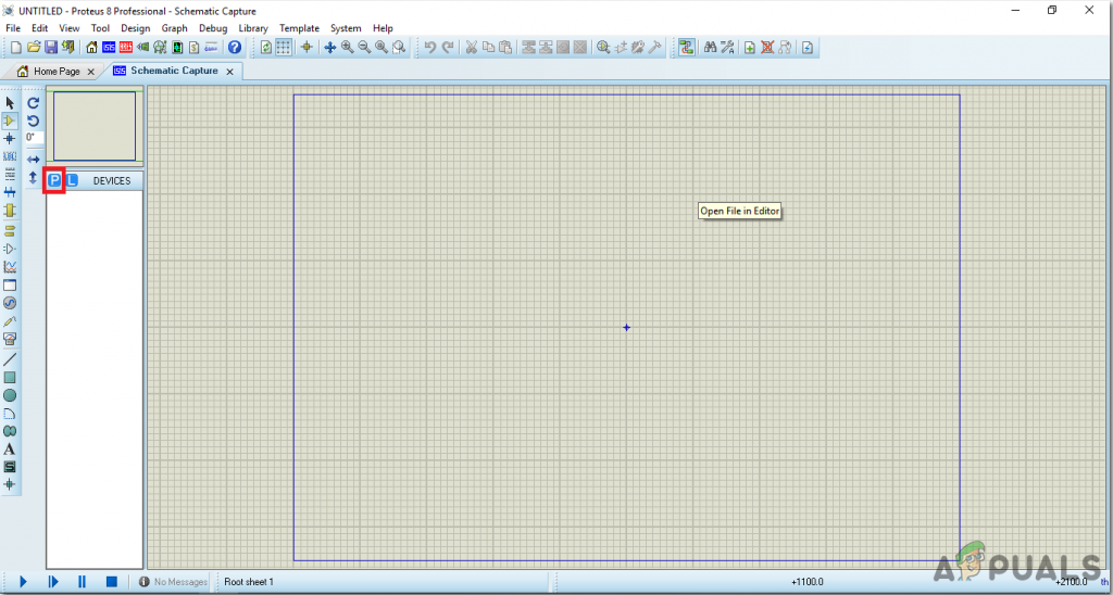
- After you download and install the Proteus software, open it. Open a new schematic by clicking the ISIS icon on the menu.
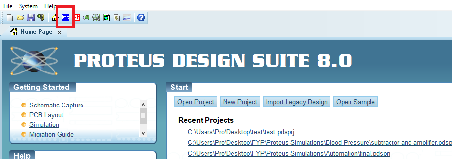
New Schematic. - When the new schematic appears, click on the P icon on the side menu. This will open a box in which you can select all the components that will be used.
New Schematic - Now type the name of the components that will be used to make the circuit. The component will appear in a list on the right side.
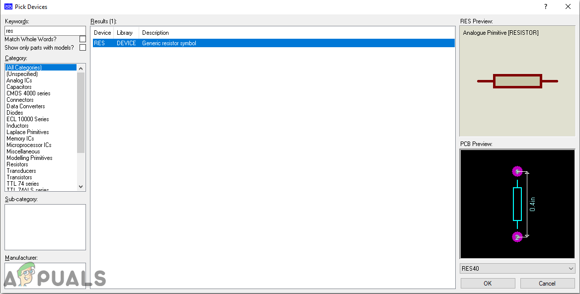
Selecting Components - In the same way, as above, search all the components. They will appear in the Devices List.
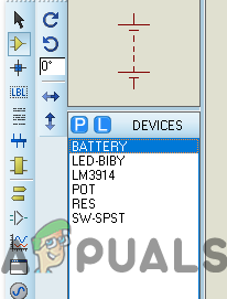
Component List
Step 5: Assembling the Circuit
Now, as we know the main connections and also the complete circuit of our project, let us move ahead and start making the hardware of our project. One thing must be kept in mind that the circuit must be compact and the components must be placed so close.
- Take a Veroboard and rub its side with the copper coating with a scraper paper.
- Now Place the components carefully and close enough so that the size of the circuit does not become very big
- Carefully make the connections using solder iron. If any mistake is made while making the connections, try to desolder the connection and solder the connection again properly, but in the end, the connection must be tight.
- Once all the connections are made, carry out a continuity test. In electronics, the continuity test is the checking of an electric circuit to check whether current flow in the desired path (that it is in certainty a total circuit). A continuity test is performed by setting a little voltage (wired in arrangement with a LED or commotion creating part, for example, a piezoelectric speaker) over the picked way.
- If the continuity test passes, it means that the circuit is adequately made as desired. It is now ready to be tested.
- Connect the battery to the circuit.
- Adjust the potentiometer so that the LED D1 starts glowing.
- Now start increasing the input voltage. You will observe that each LED will glow after an increment of 1V.
The circuit will look like the image below:
Limitations of this circuit
There are some limitations to this circuit. Some of them are given below:
- This battery level indictor works only for small voltages.
- The values of the components are theoretical, they may need a modification in practical.
Applications
The wide range of this circuit of battery level indicator includes:
- We can measure the battery level of a car by using this circuit.
- The inverter status can be calibrated by using this circuit.


