How To Make A Digital DC Voltmeter Using Arduino?
A Voltmeter is a voltage measuring device that is used to measure the voltage on certain points in an electrical circuit. Voltage is the potential difference that is created between two points in an electrical circuit. There are two types of voltmeters. Some voltmeters are designed to measure the voltage of DC circuits and other voltmeters are intended to measure the voltage in AC circuits. These voltmeters are further characterized into two categories. One is digital voltmeter which shows the measurements on a digital screen and the other is an analog voltmeter that uses a needle to point on the scale to show us the exact reading.
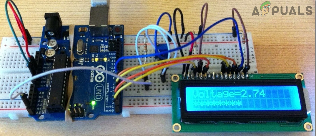
In this project, we are going to make a voltmeter using Arduino Uno. We will explain two configurations of a digital voltmeter in this article. In the first configuration, the microcontroller will be able to measure voltage in the range of 0 – 5V. In the second configuration, the microcontroller will be able to measure the voltage in the range of 0 – 50V.
How To Make a Digital Voltmeter?
As we know that there are two types of voltmeters, analog voltmeter, and digital voltmeter. There are some further types of Analog voltmeters that are based on the construction of the device. Some of these types include Permanent Magnet Moving Coil Voltmeter, Rectifier Type Voltmeter, Moving Iron Type Voltmeter, etc. The main purpose of introducing the Digital Voltmeter in the market was due to the greater probability of errors in analog voltmeters. Unlike analog voltmeter, which uses a needle and a scale, the digital voltmeter shows the readings directly in digits on the screen. This removes the possibility of Zero Error. The percentage of error is reduced fro 5% to 1% when we have shifted from analog voltmeter to digital voltmeter.
Now as we know the abstract of this project, let us gather some more information and start making a digital voltmeter using Arduino Uno.
Step 1: Collecting The Components
The best approach to start any project is to make a list of components and going through a brief study of these components because no one will want to stick in the middle of a project just because of a missing component. A list of components that we are going to use in this project is given below:
- No products found.
- No products found.
- No products found.
- No products found.
- 100k-ohm Resistor
- No products found.
- No products found.
- No products found.
Step 2: Studying The Components
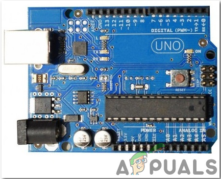
Arduino UNO is a microcontroller board which comprises of a microchip ATMega 328P and is developed by Arduino.cc. This board has a set of digital and analog data pins that can be interfaced with other expansion boards or circuits. This board has 14 Digital pins, 6 Analog pins, and programmable with the Arduino IDE (Integrated Development Environment) via a type B USB cable. It requires 5V to power ON and a C Code to operate.
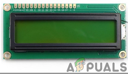
LCDs are seen in every electronic device which has to display some text or digit or any picture to the users. An LCD is a display module, in which liquid crystal is used to produce a visible image or text. A 16×2 LCD Display is a very simple electronic module that displays 16 characters per line and a total of two lines on its screen at a time. A 5×7 pixel matrix is used to display a character in these LCDs.
A Breadboard is a solderless device. It is used to make and test temporary prototype electronic circuits and designs. Most of the electronic components are simply connected to a breadboard just by inserting their pins in the breadboard. A strip of metal is laid down the holes of the breadboard and the holes are connected in a specific way. The connections of the holes are shown in the diagram below:

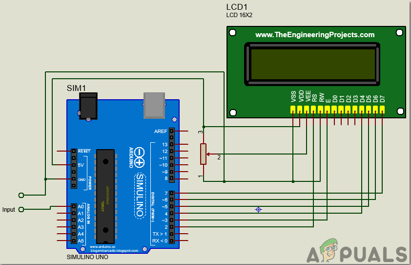
Step 3: Circuit Diagram
The first circuit whose range of measurement is from 0 to 5V is shown below:
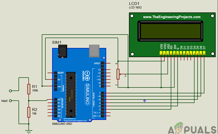
The second circuit whose measurement range is from 0 to 50V is shown below:
Step 4: Working Principle
The working of this project of Arduino based digital DC voltmeter is explained here. In the digital voltmeter, the voltage that is measured in the analog form will be converted to its corresponding digital value using an Analog to Digital Converter.
In the first circuit whose measurement range is from 0 to 5V, the input will be taken on Analog pin0. The analog pin will read any value from 0 to 1024. Then this analog value will be converted to digital by multiplying it by total voltage, which is 5V and dividing it by total resolution, which is 1024.
In the second circuit, as the range is to be increased from 5V to 50V, a voltage divider configuration must be made. The voltage divider circuit is made by using a 10k-ohm and a 100k-ohm resistor. This voltage divider configuration helps us to bring the input voltage to the range of Arduino Uno’s analog input.
All the mathematical calculations are done in the programming of Arduino Uno.
Step 5: Assembling the Components
The connection of the LCD module to the Arduino Uno board is the same in both of the circuits. The only difference is that in the first circuit, the input range is low, so it is directly sent to the analog pin of the Arduino. In the second circuit, a voltage divider configuration is used on the input side of the Microcontroller board.
- Connect the Vss and Vdd pin of the LCD module to the ground and 5V of the Arduino board respectively. The Vee pin is the pin that is used to adjust the constraints of the display. It is connected to the potentiometer whose one pin is connected to 5V and the other is connected to ground.
- Connect the RS and E pin of the LCD module to the pin2 and pin3 of the Arduino board respectively. The RW pin of the LCD is connected to the ground.
- As we will use the LCD module in 4-bit data mode, so its four pins D4 to D7 are used. D4-D7 pins of the LCD module are connected to the pin4-pin7 of the microcontroller board.
- In the first circuit, there is no additional circuitry on the input side because the maximum voltage to be measured is 5V. In the second circuit, as the measurement range is from 0-50V, a voltage divider configuration is made using a 10k-ohm and a 100k-ohm resistor. It must be noted that all the grounds are common.
Step 6: Getting Started With Arduino
If you are not familiar with Arduino IDE before, don’t worry because below, you can see clear steps of burning code on the microcontroller board using Arduino IDE. You can download the latest version of Arduino IDE from here and follow the steps mentioned below:
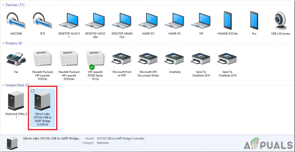
- When the Arduino board is connected to your PC, open “Control panel” and click on “Hardware and Sound”. Then click on “Devices and Printers”. Find the name of the port to which your Arduino board is connected. In my case it is “COM14” but it may be different on your PC.
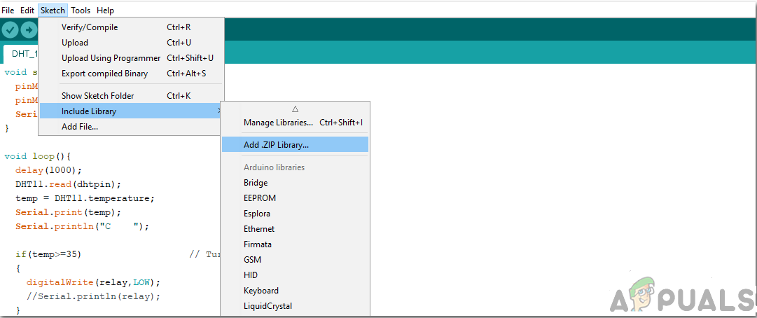
Finding Port - We will have to include a library to use the LCD Module. The library is attached below in the download link along with the code. Go to Sketch > Include Library > Add .ZIP Library.
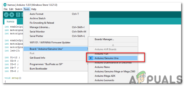
Include Library - Now open the Arduino IDE. From Tools, set the Arduino board to Arduino / Genuino UNO.
Setting Board - From the same Tool menu, set the port number that you saw in the control panel.
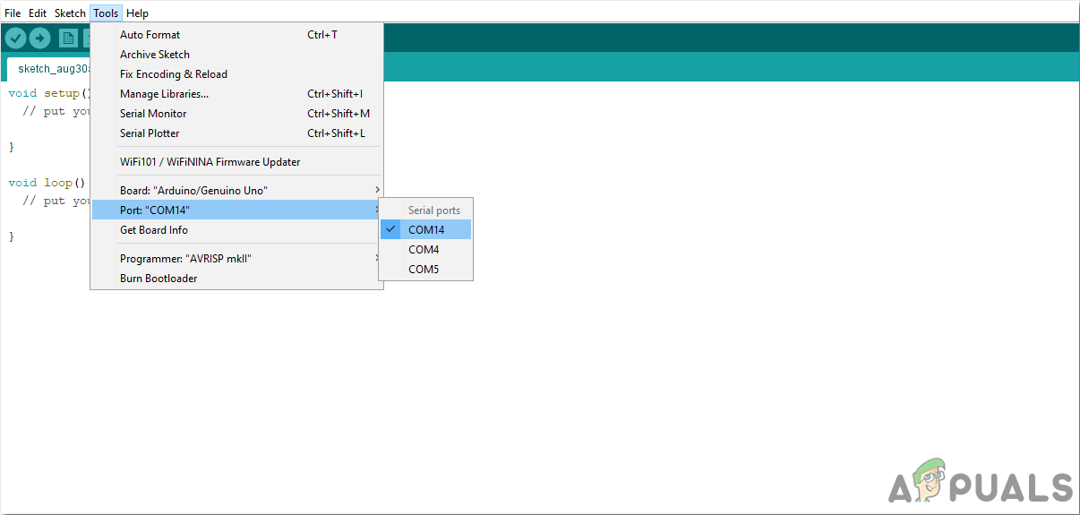
Setting Port - Download the code attached below and copy it to your IDE. To upload the code, click on the upload button.
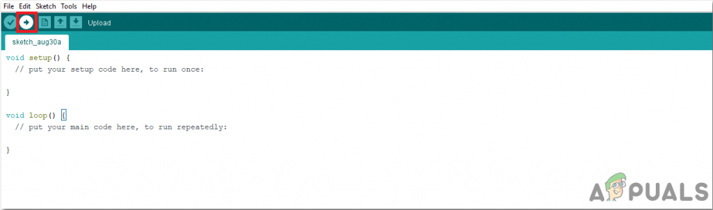
Upload
You can download the code by clicking here.
Step 7: Code
The code is quite simple and well commented. But still, some it is explained below.
1. At the start, the library is used so that we can interface the LCD module with the Arduino Uno board and program it accordingly. Than pins of Arduino board are initialized that will be used to connect with the LCD module. Then different variables are initialized to store values on the run time which will be used later in calculations.
#include "LiquidCrystal.h"           // include library to interface LCD module with Arduino board
LiquidCrystal lcd(2, 3, 4, 5, 6, 7); // pins of LCD module to be used
float voltage = 0.0;
float temp=0.0;                      // variable to store digital vaue of the input
int analog_value;                    // variable to store analog value at the input
2. void setup() is a function that runs only once when the device starts or the enable button is pressed. Here we have initialized the LCD to start. When the LCD will start the text “Arduino Based Digital Voltmeter” will be displayed. Baud Rate is also set in this function. Baud Rate is the speed in bits per second by which the Arduino communicates with the external devices.
void setup()
{
lcd.begin(16, 2);               // start communication with LCD
lcd.setCursor (0,0);            // start the cursor from the beginning
lcd.print(" Arduino based ");   // Print text in first line
lcd.setCursor(0,1);             // Move the cursoor to the next line
lcd.print("Digital Voltmeter"); // print text in second line
delay(2000);                    // wait for two secnds
}
3. void loop() is a function that runs continuously in a loop. Here the analog value is being read on the input side. Then this analog value is converted to digital form. A condition is applied and the final measurements are displayed on the LCD screen
void loop()
{
analog_value = analogRead(A0);        // Reading the analog value
temp = (analog_value * 5.0) / 1024.0; // onverting the analog value in digital

voltage = temp/(0.0909);
if (voltage < 0.1)
{
voltage=0.0;
}
lcd.clear();                          // Clear any text on the LCD
lcd.setCursor(0, 0);                  // Mve the cursor to the initial position
lcd.print("Voltage= ");               // Print Voltgae=
lcd.print(voltage);                   // Print the final digital value of voltage
lcd.setCursor(13,1);                  // move the cursor
lcd.print("V");                       // print the unit of voltage
delay(30);                            // wait for 0.3 seconds
}
Applications
Some of its applications of a digital voltmeter include:
- The circuit made above can be used to measure different ranges of voltages with high precision in any electrical circuit.
- If we make slight changes in the circuit, the Microcontroller will be able to measure the voltage in AC circuits as well.


