How To Sync Lights In Your House To The Weather Outside?
There are street lights outside our homes, on balconies or in gardens that need to be switched ON or OFF manually. We can use Philips Hue lights at our homes that vary their brightness and color according to the weather outside themselves but in order to do so we have to replace all of the bulbs in our homes and secondly, we have to pay for the application for operating those bulbs that are available on Playstore and iOS. Hence, we will design an electronic circuit at our home that switches lights according to the weather outside and also generates an alert if rainfall is about to start. The circuit is not very complex and can be prepared by anyone who has some basic knowledge regarding electrical components like resistors, capacitors, and transistors.
How To Integrate Basic Electrical Components For Designing Circuit?
Now as we know the abstract of the project, let us move forward and gather different information to start working. We will first make a list of the components and then assemble all the components together to make a working system. We will make this circuit on a PCB board and then place it outside so that it can detect the weather properly.
Step 1: Components Needed (Hardware)
Before starting any project, if we want to avoid the fear of getting stuck in the middle of the project, we should have a complete list of all the components that we will need while working on the project. This is an excellent approach that saves a lot of time and effort. A complete list of all the components that are used in this project is given below. All these components are easily available in the market.
- No products found.
- FeCl3
- PCB Board
- Soldering Iron
- Hot Glue Gun
- No products found.
Step 2: Components Needed (Software)
- Proteus 8 Professional (Can be downloaded from Here)
After downloading the Proteus 8 Professional, design the circuit on it. I have included software simulations here so that it may be convenient for beginners to design the circuit and make appropriate connections on the hardware.
Step 3: Working Principle
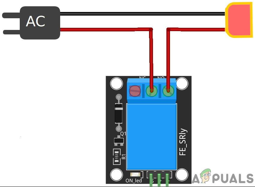
The circuit will be responsible for turning the lights ON and OFF according to the weather outside. The circuit will comprise two portions. The first portion will be designed for detecting Rainfall outside and as soon as the rainfall starts the Relay module will be triggered and the lights that will be connected to the module will start glowing. The buzzer will also be connected in this portion of the circuit and it will also be triggered when the rain starts hence it will act as an alarm for the people inside the house that the rain is about to start. The second portion of the circuit will be responsible for switching lights during the sunrise and sunset. The backbone of this circuit will be LDR (Light Dependent Resistor) because it varies its resistance with the intensity of light. The resistance of an LDR is inversely proportional to the intensity of light which means greater the intensity of light, lower the resistance of LDR. The Sensitivity of the LDR module can be changed by using a potentiometer knob on the module.
Step 4: Simulating the circuit
Before making the circuit it is better to simulate and examine all the readings on a software. The software we are going to use is the Proteus Design Suite. Proteus is a software on which electronic circuits are simulated:
- After you download and install the Proteus software, open it. Open a new schematic by clicking the ISIS icon on the menu.
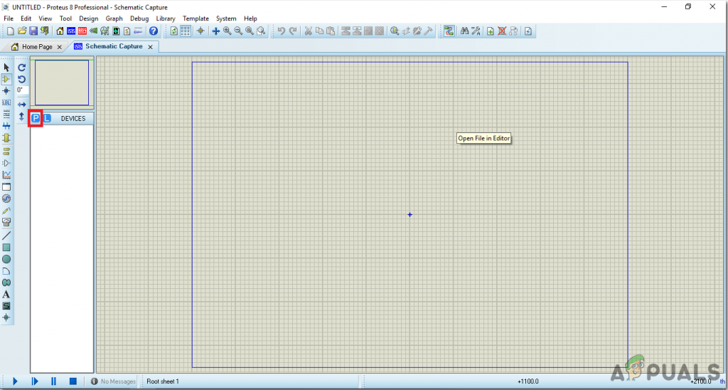
New Schematic - When the new schematic appears, click on the P icon on the side menu. This will open a box in which you can select all the components that will be used.
- Now type the name of the components that will be used to make the circuit. The component will appear in a list on the right side.
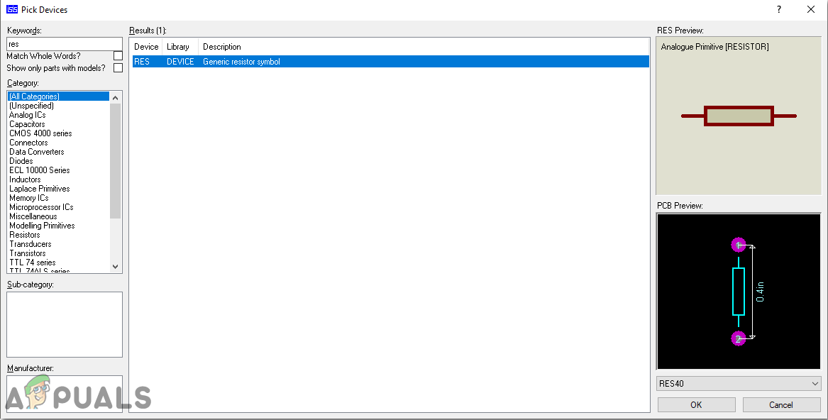
Selecting Components - In the same way, as above, search all the components as above. They will appear in the Devices List.
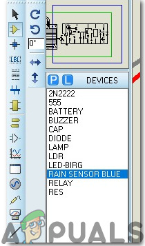
Component List
Step 5: Make a PCB Layout
As we are going to make the hardware circuit on a PCB, We need to make a PCB layout for this circuit first.
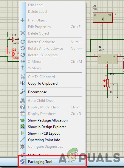
- To make the PCB layout on Proteus, we first need to assign the PCB packages to every component on the schematic. to assign packages, right mouse clicks on the component you want to assign the package and select Packaging Tool.
Assign Packages - Click on the ARIES option on the top menu to open a PCB schematic.
- From the Components List, Place all the components on the screen in a design you want your circuit to look like.
- Click on the track mode and connect all the pins that the software is telling you to connect by pointing an arrow.
Step 6: Circuit Diagram
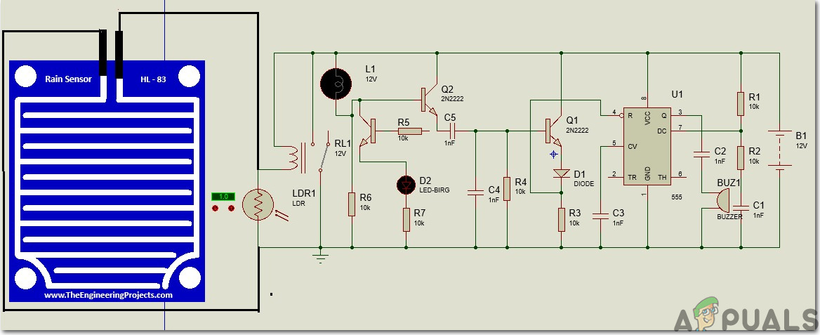
After assembling the components and wiring them the circuit diagram should look like this:
Step 7: Assembling The Hardware
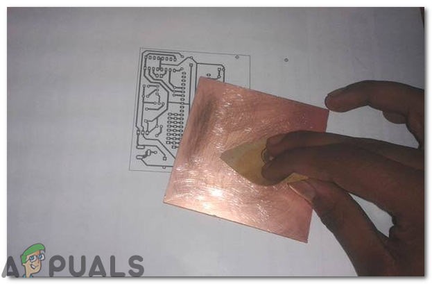
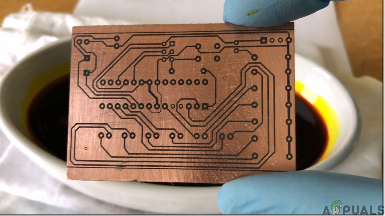
As we have now simulated the circuit on software and it is working perfectly fine. Now let us move ahead and place the components on the Printed Circuit Board. A PCB is a printed circuit board. It is a board fully coated with copper on one side and fully insulating from the other side. Making the circuit on the PCB is comparatively a lengthy process. After the circuit is simulated on the software, and its PCB layout is made, the circuit layout is printed on a butter paper. Before placing the butter paper on the PCB board use a scrapper to rub the board so that the copper layer on board is diminished from top of the board.
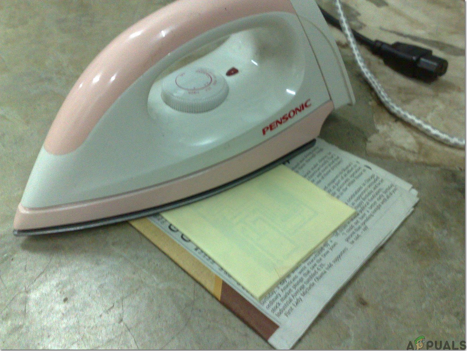
Then the butter paper is placed on the PCB board and ironed until the circuit is printed on the board (It takes approximately five minutes).
Now, when the circuit is printed on the board, it is dipped into the FeCl3 solution of hot water to remove extra copper from the board, only the copper under the printed circuit will be left behind.
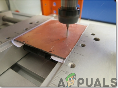
After that rub the PCB board with the scrapper so the wiring will be prominent. Now drill the holes in the respective places and place the components on the circuit board.
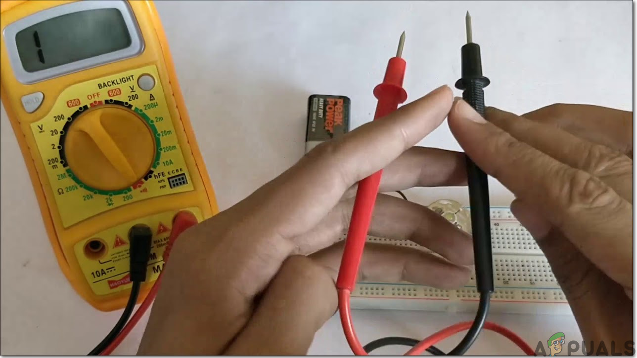
Solder the components on the board according to the circuit diagram given above. Finally, check the continuity of the circuit and if discontinuity occurs at any place de-solder the components and connect them again. Apply hot glue gun on the circuit terminals so the battery may not be detached if any pressure is applied.
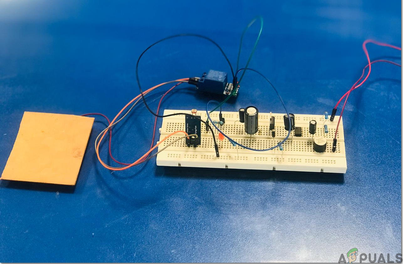
Step 8: Test The Circuit And Design Its Covering
Now, as our hardware is ready we will place it outside the house at a suitable place were sunlight and rainfall falls on it. Place it outside in the day time and wait for the sunlight to fall on it. In my case have connected all bedroom lights, terrace lights and garage lights to the second portion of the circuit and as soon as the sun sets and the resistance of the LDR increases these lights are turned ON. Secondly, when the rainfall starts and water starts falling on the raindrop sensor the lights of the kitchen and the living room will turn ON along with the buzzer which shows the indication of rain and they will turn OFF as the rain is stopped. I have included the buzzer in the circuit so that if you have washed your clothes and placed them outside for drying you could make proper arrangements if the rain has started. If you are well familiar with the electric circuits then you can change the connections of the circuit and control the lights of your own choice. Connect the 12V adapter with the circuit to turn it ON or you can use 12V DC battery for powering it too.
After testing the circuit place it in a covering so that it doesn’t become short when exposed to the water. You can place it inside a lunch box or design its casing by using any other water-resistant material. It can be designed easily at home.
Recommendations
- It is better to design the rain sensor at home by using a small piece of PCB. Print a zigzag pattern and paste it on the board and perform etching as shown above.
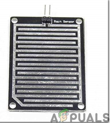
Raindrop Sensor
Now, you’ve designed the circuit for your home that will be responsible for operating the lights of your home. Don’t forget to share your experience after making your own prototype and keep visiting our website in the future for interesting engineering projects.


FeCl3
PCB Board
Soldering Iron
Hot Glue Gun
Digital Multi MeterI think drill and drill bit (what size diameter?) should be added to this list.