Assembling a Smart Helmet at Home
A helmet has immense importance for a biker and most of the time we have seen that it has saved the lives of people. If a person is wearing a helmet the risk of head and brain injuries is reduced to a great extent. The ordinary helmets that are easily available in the market don’t ensure 100% safety because of no alcohol detection feature, no notification after an accident, etc. The features that I have mentioned are available in the Smart Helmets that mostly Heavy bikers wear and it costs around $300-400. Keeping this in view today I will design a budget-friendly Smart Helmet that will have features like alcohol detection, accident notification, GPS tracker, etc. This helmet can be easily designed at home without any hassles if one has some knowledge about circuits and he/she can do some software-based simulations. Follow the procedure given below step by step to complete this project.
How To Assemble Basic Electronic Components With GSM Module?
It is better to draw a rough notebook sketch of the helmet before starting this project because it will allow us to understand the placement of components better and assembling the circuit will be easy for us. An excellent approach before starting the work is to make a complete list of all the components to save time and to avoid the chance of getting stuck in the middle of the project. A complete list of all the components that are easily available in the market is given below:
Step 1: Components Used (Hardware)
Step 2: Components Used (Software)
- Proteus 8 Professional (Can be downloaded from Here)
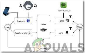
Step 3: Block Diagram
To demonstrate the working of the helmet well I have made a block diagram that is shown below:
Step 4: Working Principle
All types of Arduino boards can be used in the project but I preferred Arduino Nano because two of them will be placed inside the helmet and they require less space. I have used Alcohol sensor MQ-3 to determine the quantity of Alcohol the driver has taken and this level is indicated with a Bi-Colour LED. If the driver has taken a large amount of alcohol the LED turns Red and SMS notification is sent to the number mentioned in the code through a GPS. If the LED turns Yellow it means that the alcohol level is moderate and if it turns Green it means that the driver isn’t drunk. Hence, this ensures the safety of the driver and the risk of an accident is minimized to a great extent. The Ultrasonic sensor will be placed at the back of the helmet and it will keep calculating the distance between the rider and the vehicles at the back. If a vehicle is approaching the rider at a very high speed the ultrasonic sensor will send a signal to Arduino to trigger the buzzer and hence the rider will get aside and let the vehicle pass by. I have included the GPS module to send alerts to the specific mobile number in case of an accident. For detecting the accident the vibration sensor is included in the circuit that can be tuned to a specific level of vibration and immediately tells the GSM module to send a notification to certain numbers as a call for help. Two Arduino’s will be used in this project. One will be connected to the Ultrasonic Sensor and Alcohol Sensor and the other one will be connected to the GSM module and the vibration sensor. There will be two separate circuits that would be placed inside the helmet and they will be connected to the same battery. Note: The variable capacitor present in the vibration sensor will be tuned.
Step 5: Assembling The Circuit On Proteus
- After you download and install the Proteus software, open it. Open a new schematic by clicking the ISIS icon on the menu.
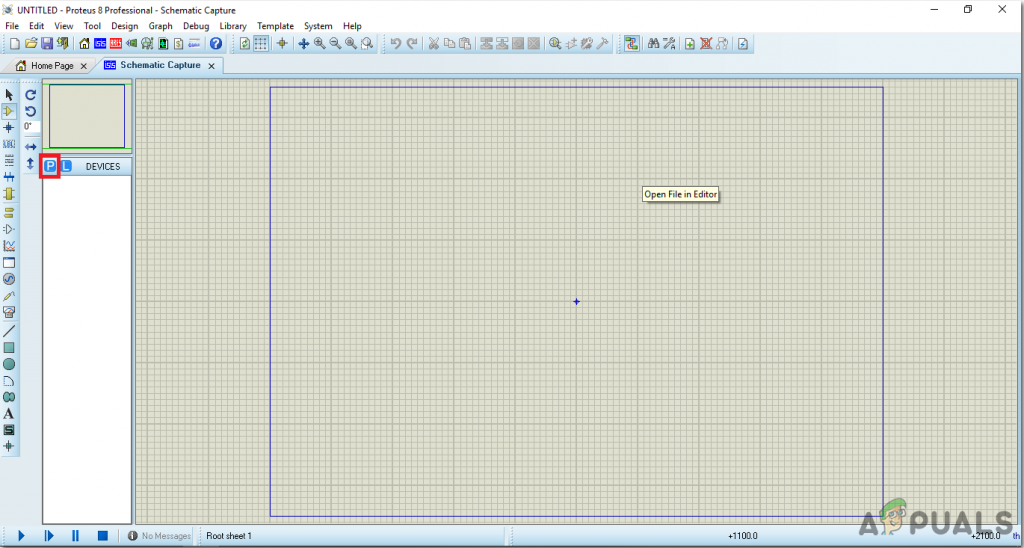
New Schematic - When the new schematic appears, click on the P icon on the side menu. This will open a box in which you can select all the components that will be used.
- Now type the name of the components that will be used to make the circuit. The component will appear in a list on the right side.
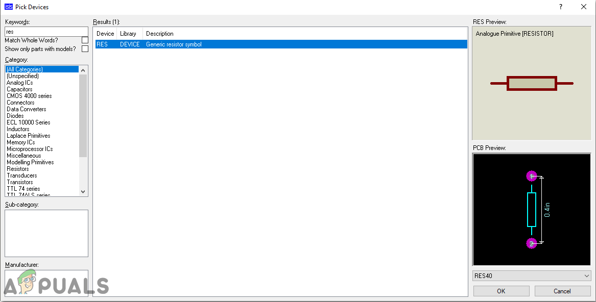
Selecting Components - In the same way, as above, search all the components as above. They will appear in the Devices List.
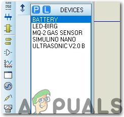
Component List
Step 6: Circuit Diagrams
Assemble your hardware circuit according to the circuit diagrams shown below:
- Circuit Diagram # 1:
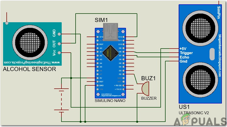
Circuit Diagram - Circuit Diagram # 2:
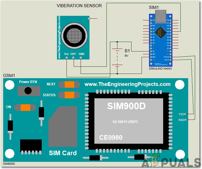
Circuit Diagram
Step 7: Getting Started With Arduino
If you are not familiar with Arduino IDE before, don’t worry because below, you can see clear steps of burning code on the microcontroller board using Arduino IDE. You can download the latest version of Arduino IDE from here and follow the steps below:
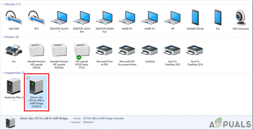
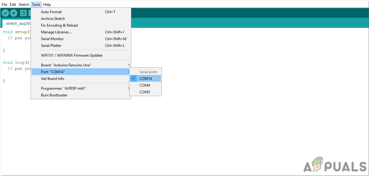
- Connect your Arduino Nano board to your laptop and open the control panel. in the control panel, click on Hardware and Sound. Now click on Devices and Printers. Here, find the port to which your microcontroller board is connected. In my case it is COM14 but it is different on different computers.
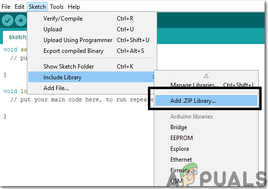
Finding Port - We will have to include a library to use the GSM Module. Go to Sketch > Include Library > Add .ZIP Library.
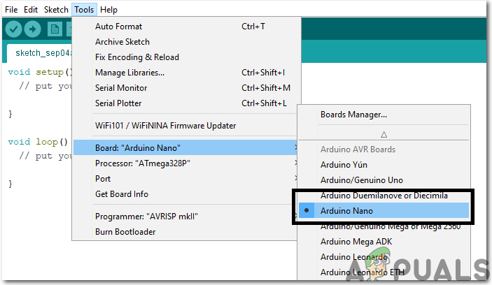
Include Library - Click on the Tool menu and set the board to Arduino Nano.
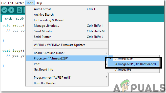
Setting The Board - In the same Tool menu, Set the Processor to ATmega328P (Old Bootloader).
Setting The Processor - In the same Tool menu, set the port to the port number that you observed before in the Devices and Printers.
Setting Port - Download the code attached below and paste it into your Arduino IDE. Click on the upload button to burn the code on your microcontroller board.
Upload
Step 8: Code Of The Project
The code is a bit lengthy but it is really simple. Some of its chunks are explained below:
1. At the start, libraries are included so that we can easily communicate with special peripheral devices.
#include "Adafruit_FONA.h"
#include <SoftwareSerial.h>
SoftwareSerial fonaSS = SoftwareSerial(FONA_TX, FONA_RX);
SoftwareSerial *fonaSerial = &fonaSS;
Adafruit_FONA fona = Adafruit_FONA(FONA_RST);
2. Then pins are defined on the Arduino nano which will be used to connect the external sensors to the microcontroller. These pins will be responsible for the Input and Output of the data in the microcontroller.
#define FONA_RX 2
#define FONA_TX 3
#define FONA_RST 4
//vibration sensor
#define VS 10
#define R 2
#define Y 4
#define MQ3 A0
# define buzzer 9 .
#define triggerPin 7 //triggering on pin 7
#define echoPin 8 //echo on pin 8
3. Then different variables are initialized which will later be used in the calculation processes during the run time of the code. A buffer is also made that will be used with the GSM module.
int gaslevel;
// this is a large buffer for replies
char replybuffer[255];
uint8_t readline(char *buff, uint8_t maxbuff, uint16_t timeout = 0);
uint8_t type;
int vs=10;
int shockVal = HIGH;
4. void setup() is a function that is executed only once when the microcontroller is powered up or the enable button is pressed. the baud rate is set in this function which is basically the speed in bits per second by which the microcontroller communicates with the external sensors. All the pins of the Arduino are initialized here that they will be used to take input from the sensor or send output to another device. GSM module is also initialized in this function.
void setup() {
  Serial.begin(9600);
  //we'll start serial comunication, so we can see the distance on the serial monitor
  Serial.println("Tech Ponder's UltraSonic Sensor Tutorial");
  pinMode(triggerPin, OUTPUT); //defining pins
  pinMode(echoPin, INPUT);
  pinMode(buzzer, OUTPUT);
  digitalWrite(buzzer,LOW);
  pinMode(MQ3,INPUT);
  pinMode(R,OUTPUT);
  pinMode(Y,OUTPUT);
  pinMode(vs, INPUT);

  while (!Serial);
  //  Serial.println(F("FONA basic test"));
  //  Serial.println(F("Initializing....(May take 3 seconds)"));
  fonaSerial->begin(4800);
  if (! fona.begin(*fonaSerial)) {
    //    Serial.println(F("Couldn't find FONA"));
    while (1);
  }
  type = fona.type();
  // Serial.println(F("FONA is OK"));
  // Serial.print(F("Found "));
  switch (type) {
    case FONA800L:
    //     Serial.println(F("FONA 800L")); break;
    case FONA800H:
    //     Serial.println(F("FONA 800H")); break;
    case FONA808_V1:
    //    Serial.println(F("FONA 808 (v1)")); break;
    case FONA808_V2:
    //    Serial.println(F("FONA 808 (v2)")); break;
    case FONA3G_A:
    //    Serial.println(F("FONA 3G (American)")); break;
    case FONA3G_E:
    //    Serial.println(F("FONA 3G (European)")); break;
    default:
    //    Serial.println(F("???"));
    break;
  }
  // Print module IMEI number.
  char imei[15] = {0}; // MUST use a 16 character buffer for IMEI!
  uint8_t imeiLen = fona.getIMEI(imei);
  if (imeiLen > 0) {
    //   Serial.print("Module IMEI: "); Serial.println(imei);
  }
}
5. void loop() is a function that runs repeatedly in a loop while the microcontroller is powered on. A code is written for an ultrasonic sensor that if it measures a distance less then a specific value, it will send a signal to the buzzer which will be used to notify the rider that a vehicle is approaching near. The gas sensor is also integrated here. Three LEDs are used in order to tell that if the rider is heavily, partially or less drunk. If green LED glows, it means that the rider is good to go. At the end of this function, another function is called named viberationFun().
void loop() {
  int duration, distance; //Adding duration and distance
  digitalWrite(triggerPin, HIGH); //triggering the wave(like blinking an LED)
  delay(10);
  digitalWrite(triggerPin, LOW);
  duration = pulseIn(echoPin, HIGH); //a special function for listening and waiting for the wave
  distance = (duration/2) / 29.1;
  delay(1000);
  Serial.print(distance); //printing the numbers
  Serial.print("cm"); //and the unit
  Serial.println(" "); //just printing to a new line
  if (distance < 35)
  {
     digitalWrite(buzzer,HIGH);
     Serial.println("Buzzer On");
  }
  digitalWrite(buzzer,LOW);
  gaslevel=(analogRead(MQ3));
  gaslevel=map(gaslevel,0,1023,0,255);

  if(gaslevel > 100 && gaslevel <= 300){//gaslevel is greater than 100 and less than 300
  digitalWrite(R,LOW);//RED led is off
  _delay_ms(500);//delay
  digitalWrite(Y,HIGH);//YELLOW led is on
  _delay_ms(500);
  }
  else if(gaslevel > 300 && gaslevel <= 600){//gaslevel is greater than 300 and less than 600
    digitalWrite(Y,LOW);//YELLOW led is off
    _delay_ms(500);
    digitalWrite(R,HIGH);//RED led is on
  }
  else
  {
    digitalWrite(R,LOW);//red led is off
    digitalWrite(Y,LOW);//YELLOW led is off
  }
  Serial.println(gaslevel);//print values on serial monitor
  _delay_ms(100);

  viberationFun();
}
6. viberationFun() is a function that will detect if the bike had a collision with another object or not. If it detects any collision, it will send a message to the numbers that are specified in the code. In this way, the news of the accident will reach someone else who will take the necessary steps to save the rider.
void viberationFun(){
  shockVal = digitalRead (vs) ;
        int t=0;
        char sendto[11]="YOUR NUMBER";
        char sendto1[11]="YOUR NUMBER 2";
        char message[27]="Accident has been detected";
        if(shockVal == HIGH || shockVal == 1){
          if(t==0){
            Serial.println(shockVal);
        if (!fona.sendSMS(sendto, message) && !fona.sendSMS(sendto1, message)) {
          Serial.println(F("Failed"));
        } else {
          Serial.println(F("Sent!"));
          t=1;
        }
        delay(1000);
        if(!fona.sendSMS(sendto1, message)) {
          Serial.println(F("Failed"));
        } else {
          Serial.println(F("Sent!"));
          t=1;
        }
         }
        }else{
          t=0;
        }
}
Step 9: Assembling The Hardware
Now, as we know the main connections and also the complete circuit of our project, let us move ahead and start making the hardware of our project. One thing must be kept in mind that the circuit must be compact and the components must be placed close. Veroboard is the better option as compared to the breadboard because connections get loose on the breadboard and short circuit can take place and breadboard has more weight as compared to the Veroboard. The circuit placed on the Veroboard will be very small so it can be fitted inside the helmet easily.
- Take a Veroboard and rub its side with the copper coating with a scraper paper.
- Now Place the components carefully and close enough so that the size of the circuit does not become very big.
- Carefully make the connections using solder iron. If any mistake is made while making the connections, try to desolder the connection and solder the connection again properly, but in the end, the connection must be tight.
- Once all the connections are made, carry out a continuity test. In electronics, the continuity test is the checking of an electric circuit to check whether current flow in the desired path (that it is in certainty a total circuit). A continuity test is performed by setting a little voltage (wired in arrangement with a LED or commotion creating part, for example, a piezoelectric speaker) over the picked way.
- If the continuity test passes, it means that the circuit is adequately made as desired. It is now ready to be tested.
- Connect the battery to the circuit.
The rest of the circuit will be placed inside the helmet except the Ultrasonic sensor that will be mounted on the backside of the helmet to detect the vehicles coming from behind. Lipo battery is used in this project because it is a very lightweight battery and even if the rider is going on a long trip it can give better timing. Adjust the Lipo battery inside the helmet because due to harsh weather conditions like rain it can result in failure of the circuit.
Step 10: Testing
As now, the hardware is assembled and the code is also uploaded onto the microcontroller let’s go through the final step and test the circuit. Sit on the motorbike and turn ON the push button switch to activate the circuit. Start riding in your street and ask someone to approach you on the car at a high speed from behind. You will observe that the buzzer will start ringing and after that apply brakes at a high speed so that large vibration can occur. As soon as the vibration occurs an alert notification will be sent to the mobile number that you’ve mentioned in the code.
Recommendations
This is a very interesting project there are several options that can be included further in it with the help of some basic electronic components. Some of them are illustrated below:
- You can use Raspberry Pi with the Pi camera module and adjust its position in such a way that you could observe the projection on the mirror of the helmet. In this way, you would be able to get a back view of the road and it would be very helpful while overtaking, etc.
- The relay module can be connected with the ignition switch of the motorbike and it could be set in such a way that ignition turns ON only when the rider has worn the helmet.
- Small solar panels can also be attached on the top and backside of the helmet so that the need for the battery is diminished and the weight of the circuitry can further be reduced inside the helmet.


good day! where is the gps code here?