How To Make Obstacle Avoiding Robot Using Arduino?
The world is moving fast, and technology is also moving with it in the field of robotics. The applications of robotics can be seen everywhere around the world. The concept of mobile or autonomous robots who move without any external help is the most immerging field of research. There are so many types of mobile robots, for example, Self Localization and Mapping (SLAM) interpreters, Line following, Sumo Bots, etc. An obstacle avoiding robot is one of them. It uses a technique to change the path if it detects any obstacle in its way.
In this project, an Arduino based obstacle avoiding robot is designed that will use an ultrasonic sensor to detect all the obstacles in its path.
How to Avoid Obstacles using Ultrasonic Sensor?
As we know the abstract of our project, let us move a step ahead and gather some for information to start the project.
Step 1: Collecting the Components
The best approach to start any project is to make a list of complete components at the start and going through a brief study of each component. This helps us in avoiding the inconveniences in the middle of the project. A complete list of all the components used in this project is given below.
- No products found.
- No products found.
- No products found.
- No products found.
- No products found.
- Battery
Step 2: Studying the Components
Now, as we have a complete list of all the components, let us move one step forward and go through a brief study of the working of every component.
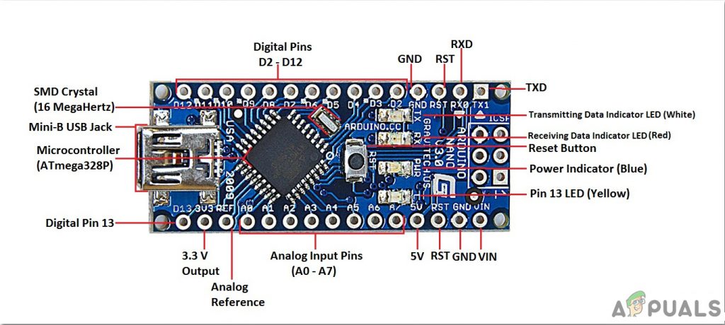
Arduino nano is a breadboard-friendly microcontroller board that is used to control or carry out different tasks in a circuit. We burn a C Code on Arduino Nano to tell the microcontroller board how and what operations to perform. Arduino Nano has exactly the same functionality as Arduino Uno but in quite a small size. The microcontroller on the Arduino Nano board is ATmega328p.
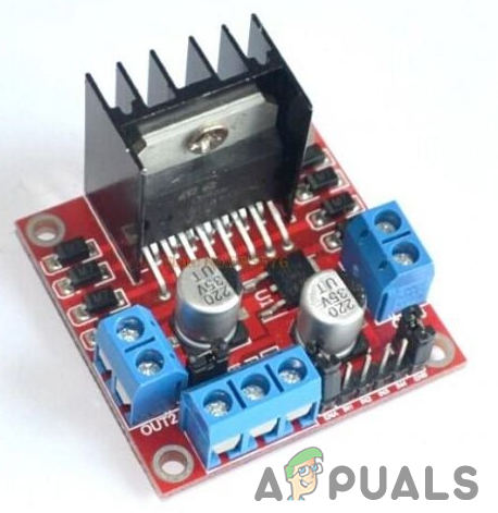
The L298N is a high current and high voltage integrated circuit. It is a dual full-bridge designed to accept standard TTL logic. It has two enable inputs that allow the device to operate independently. Two motors can be connected and operated at the same time. The speed of the motors is varied through the PWM pins. Pulse Width Modulation (PWM) is a technique in which the flow of voltage in any electronic component can be controlled. This module has an H-Bridge which is responsible for the control of rotation direction in the motors by inverting the direction of the current. The Enable pin A and Enable Pin B are used to change the speed of both of the motors. This module can operate between 5 and 35V and peak current up to 2A. The Input Pin1 and Input Pin2 and for First motor and the Input Pin3 and Input Pin4 are for the second Motor.
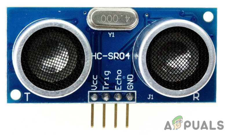
HC-SR04 board is an ultrasonic sensor which is used to determine the distance between two objects. It consists of a transmitter and a receiver. The transmitter converts the electrical signal into an ultrasonic signal and the receiver converts the ultrasonic signal back to the electrical signal. When the transmitter sends an ultrasonic wave, it reflects after colliding with a certain object. The distance is calculated by using the time, that ultrasonic signal takes to go from the transmitter and come back to the receiver.
Step 3: Assembling the Components
Now as we now know the working of most of the components used, let us start assembling all the components and produce an obstacle avoiding robot.
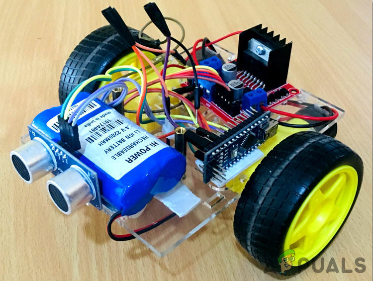
- Take a car wheel chasses and stick a breadboard on its top. Mount the Ultrasonic sensor in the front of the chasses and a battery cap behind the chasses.
- Fix the Arduino Nano board on the breadboard and attach the motor driver right behind the breadboard, on the chasses. Connect the Enable pins of bothe the motors to the Pin6 and Pin9 of Arduino nano. The In1, In2, In3 and In4 pins of the motor driver module are connected to the pin2, pin3, pin4 and pin5 of the Arduino nano respectively.
- The trig and echo pin of the ultrasonic sensor is connected to the pin11 and in10 of the Arduino nano respectively. The Vcc and ground pin of the ultrasonic sensor are connected to the 5V and ground of the Arduino Nano.
- The Motor controller module is powered by the battery. The Arduino Nano board gets the power from the 5V port of the motor driver module and the ultrasonic sensor will get its power from the Arduino nano board. the weight and energy of the batteries may become the determinative factor of its performance.
- Make sure your connections are the same as shown below in the circuit diagram.
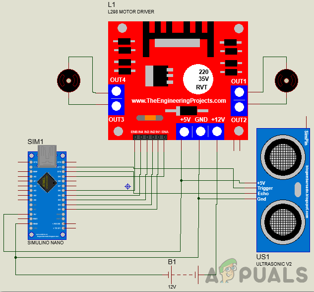
Circuit Diagram
Step 4: Getting Started with Arduino
If you are not already familiar with the Arduino IDE, don’t worry because a step by step procedure to set-up and use Arduino IDE with a microcontroller board is explained below.
- Download the latest version of Arduino IDE from Arduino.
- Connect your Arduino Nano board to your laptop and open the control panel. in the control panel, click on Hardware and Sound. Now click on Devices and Printers. Here, find the port to which your microcontroller board is connected. In my case it is COM14 but it is different on different computers.

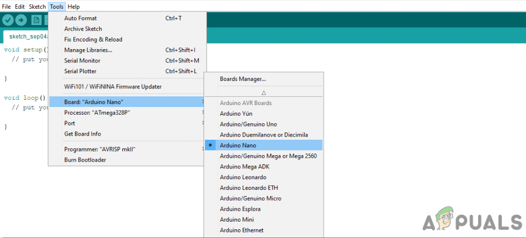
Finding Port - Click on the Tool menu. and set the board to Arduino Nano from the drop-down menu.
Setting Board - In the same Tool menu, set the port to the port number that you observed before in the Devices and Printers.

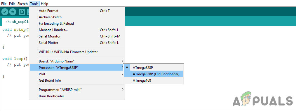
Setting Port - In the same Tool menu, Set the Processor to ATmega328P (Old Bootloader).
Processor - Download the code attached below and paste it into your Arduino IDE. Click on the upload button to burn the code on your microcontroller board.

Upload
To download the code, click here.
Step 5: Understanding the Code
The code is well commented and self-explanatory. But still, it is explained below
1. At the start of the code, all the pins of the Arduino Nano board that are connected to the ultrasonic sensor and motor driver module, are initialized. Pin6 and Pin9 are PWM pins that can vary the flow of voltage to vary the speed of the Robot. Two variables, duration, and distance are initialized to store data that will later be used to calculate the distance of the ultrasonic sensor and the obstacle.
int enable1pin=6; // Pins for First Motor
int motor1pin1=2;
int motor1pin2=3;
int enable2pin=9; //Pins For Second Motor
int motor2pin1=4;
int motor2pin2=5;

const int trigPin = 11; // Trigger Pin Of Ultrasonic Sesnor
const int echoPin = 10; // Echo Pin Of Ultrasonic Sesnor

long duration;  // variables to Calculate the distance
float distance;
2. void setup() is a function that is used to set al the pins used, as INPUT and OUTPUT. Baud Rate is defined in this function. Baud Rate is the speed of communication by which the microcontroller board communicates with the sensors integrated with it.
void setup()
{
Serial.begin(9600);
pinMode(trigPin, OUTPUT);
pinMode(echoPin, INPUT);
pinMode(enable1pin, OUTPUT);
pinMode(enable2pin, OUTPUT);
pinMode(motor1pin1, OUTPUT);
pinMode(motor1pin2, OUTPUT);
pinMode(motor2pin1, OUTPUT);
pinMode(motor2pin2, OUTPUT);
}
3. void loop() is a function that runs repeatedly in a cycle. In this function, we tell the microcontroller board how and what operations to carry out. Here, first, the trigger pin is set to send a signal which will be detected by the echo pin. Then the time that is taken by the ultrasonic signal to travel from and back to the sensor is calculated and saved in the variable duration. Then this time is used in a formula to calculate the distance of the obstacle and the ultrasonic sensor. Then a condition is applied that if the distance is more than 5ocm, the robot will move forward in a straight line and if the distance is less than 50cm, the robot will take a sharp right turn.
void loop()
{
digitalWrite(trigPin, LOW); // Sending and Detecting the Ultrasonic Signal
delayMicroseconds(2);
digitalWrite(trigPin, HIGH);
delayMicroseconds(10);
digitalWrite(trigPin, LOW);

duration = pulseIn(echoPin, HIGH); // Calulating the timme taken by the ultrasonic wave to reflect back
distance = 0.034*(duration/2); // Calulating the distance betweek thee robbot and the obstacle.

if(distance>50) // Move Forward if distance is greater than 50cm
{
digitalWrite(enable1pin, HIGH);
digitalWrite(enable2pin, HIGH);
digitalWrite(motor1pin1, HIGH);
digitalWrite(motor1pin2, LOW);
digitalWrite(motor2pin1, HIGH);
digitalWrite(motor2pin2, LOW);
}

else if(distance<50) // Sharp Right Turn if the distance is less than 50cm
{
digitalWrite(enable1pin, HIGH);
digitalWrite(enable2pin, HIGH);
digitalWrite(motor1pin1, HIGH);
digitalWrite(motor1pin2, LOW);
digitalWrite(motor2pin1, LOW);
digitalWrite(motor2pin2, LOW);
}
delay(300);
}
Applications
So here was the procedure to make an obstacle avoiding robot This obstacle avoiding technology can be sued in other applications too. Some of these applications are as follows.
- Tracking System.
- Distance Measurement Purposes.
- This can be used in automatic vacuum cleaning robots.
- This can be used in Sticks for blind people.


