How To Control Home Appliances Using MATLAB?
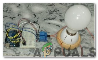
The home automation network technology was developed in the later 90’s and communication protocol used at that time was X10. Since then the concept of automation is gaining popularity and the latest protocols have been invented that are responsible for communication between electronic devices. Keeping the concept of automation in view I thought why not control all of the home appliances using the most renowned software known as MATLAB. In this project, we will design an Automation system and then control it by giving a Serial command. Software that will be used to operate this system is named MATLAB and after completing this project we will be able to control our electrical appliances by just sitting on the couch or laying on Bed.
How to Automate Your Home Appliances using MATLAB GUI?
Now let’s move towards gathering the components, assembling them together to make a circuit, making a MATLAB Graphical User Interface (GUI) and writing the code in MATLAB to automate your home appliances.
Step 1: Components Needed (Hardware)
It is always better to know about the components in detail before starting the project in order to avoid any inconvenience in the middle of the project. Below is the list of components that we are going to use:
- No products found.
- No products found.
- MAX232 IC
- No products found.
- 12V AC Bulb
- Jumper Wires For Arduino
- No products found.
- No products found.
Here, we are using an 8 relay module because we will only control eight appliances. If you want to automate a number of appliances that you have, you can use a different relay module. There are many relay modules available in the market for example, single, 8-relay, 12-relay, etc.
Step 2: Components Needed (Software)
After arranging the hardware components we will look for the software that will be used in the project. We will install the latest version of MATLAB on our laptop or PC on which we are working. The MATLAB 2019 is the latest software so its better to download MATLAB 2019. The link to the official website of Mathworks is available below for downloading the software. The Hardware Support packages are available in MATLAB 2019 for 32 bit,64-bit Windows and 64-bit Linux.
After downloading the Proteus 8 Professional, design the circuit on it. I have included software simulations here so that it may be convenient for beginners to design the circuit and make appropriate connections on the hardware.
Step 3: Studying The Components
Now as we have made a list of all the components that we are going to use in this project. Let us move a step further and go through a brief study of all the main hardware components.
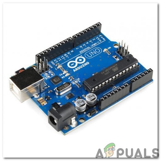
Arduino UNO: The Arduino UNO is a microcontroller board which comprises of a microchip ATMega 328P and is developed by Arduino.cc. This board has a set of digital and analog data pins that can be interfaced with other expansion boards or circuits. This board has 14 Digital pins, 6 Analog pins, and programmable with the Arduino IDE (Integrated Development Environment) via a type B USB cable. It requires 5V to power ON and a C Code to operate.
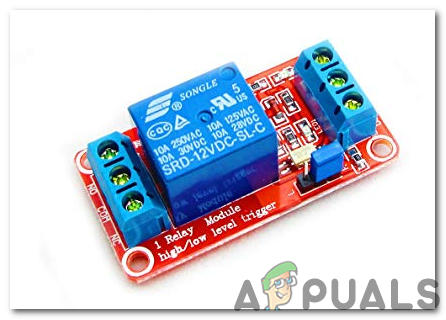
12V Relay Module: A Relay Module is a switching device. It receives a signal and switches any electronic device or appliance according to the input signal. It works in two modes, Normally Open (NO) and Normally Closed (NC). In Normally Open mode, the circuit is broken initially when the input signal to relay is LOW. In Normally Closed mode, the circuit is initially complete when the input signal is LOW.
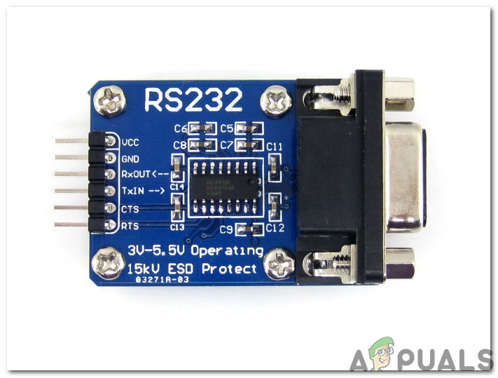
RS232 To TTL Serial Port Converter Module: This module is used for serial communication. Our Arduino UNO board has one serial communication port named as UART or USART. There are two pins on the Arduino board that are responsible for serial communication TX and RX (Pin 0 and pin 1). These two pins are also present on the RS232 module. This module is powered by 5V of Arduino and it converts 5V to 12V for operating different appliances that operate on 12V. We use this module because electronic appliances don’t operate on 5V.
Step 4: Understanding The Working Principle
After completing this project we will be able to control appliances remotely by giving the command serially. Arduino board is used for serial communication with the RS232. Appliances are connected to the Relay module and the RS232 is connected to the TX and RX pins of the Arduino and when a push-button is pressed on MATLAB a serial command is generated and it is sent to the serial port of RS232 which in return turns ON or OFF the appliance. Firstly, MATLAB is interfaced with the Arduino board and then the circuit is implemented on the hardware. If anyone has a problem regarding the interfacing of MATLAB with Arduino he/she can refer to my article named HOW TO INTERFACE ARDUINO WITH MATLAB? and then he/she will be able to implement this project on hardware. After completing this project install it to a suitable place, the preferred location is near to the socket where the wiring of the appliances is placed so that the Relay module can be installed easily there.
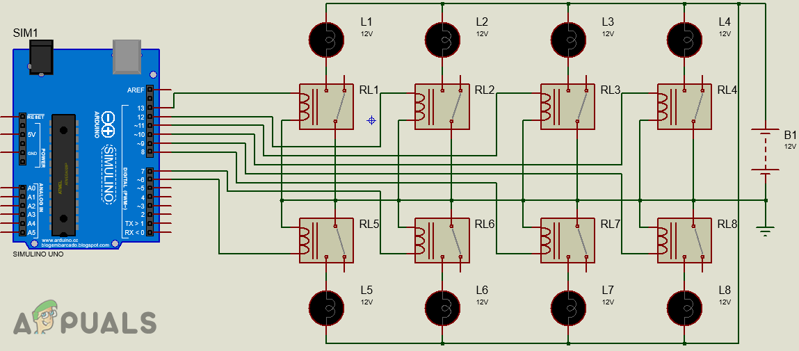
Step 5: Circuit Diagram
The proteus circuit diagram of the project will look like this. Connect the hardware components according to this circuit later on.
Step 6: Getting Started With MATLAB
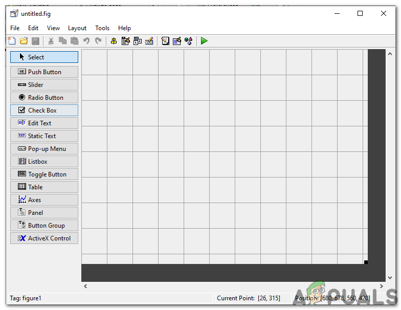
After designing the circuit on Proteus Open MATLAB and type “guide” on the command window. A dialog box will open and from that box select Blank GUI. A component palette will appear at the left and it will list the components which you want to place in your GUI.
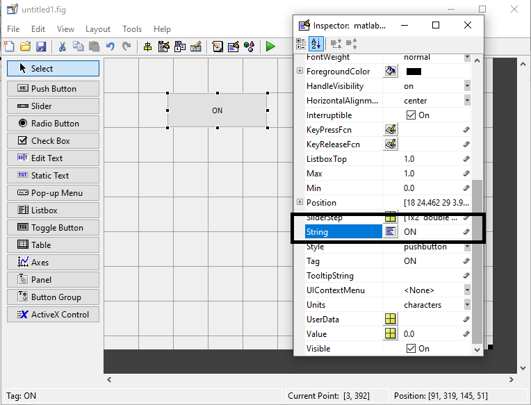
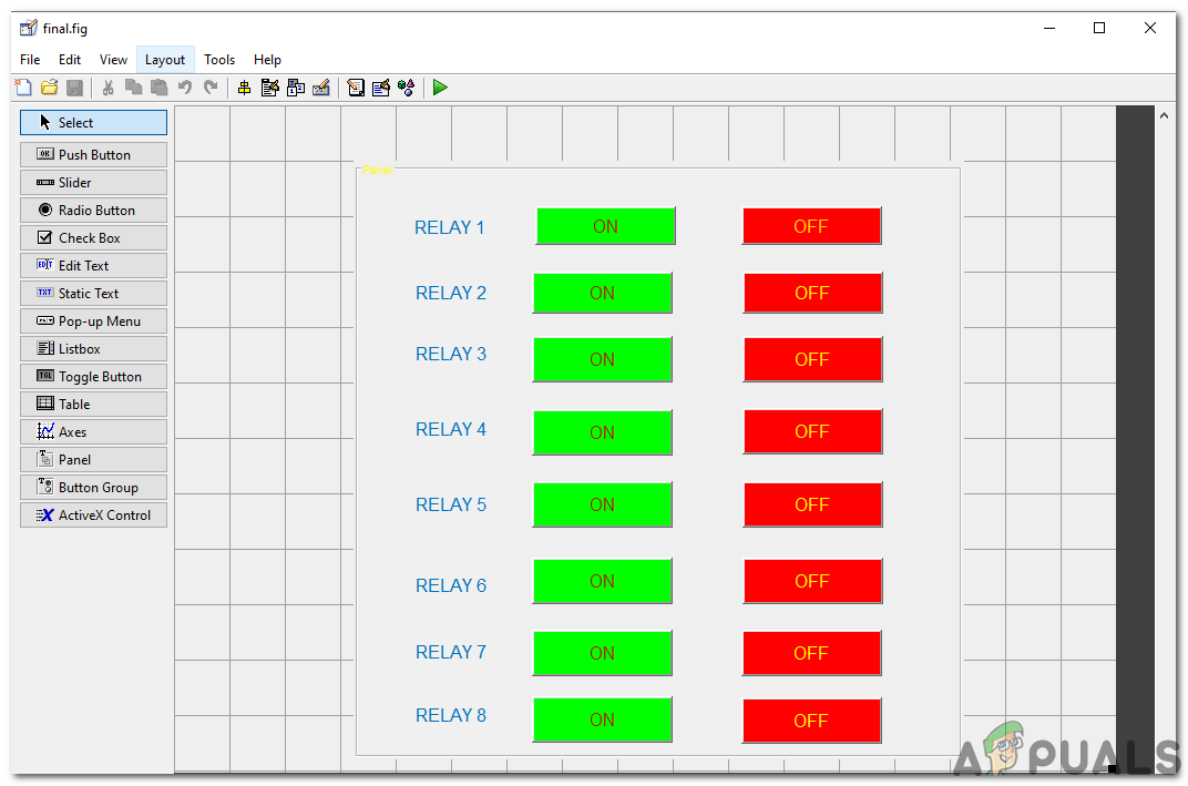
Select the push button and place 16 push buttons on the panel. Firstly, place the ON button and then place the OFF button in parallel to it. The colors and names of the buttons can be modified by double-clicking the push buttons. After clicking the pushbuttons the inspector window will open and some properties of the button can be modified there. For changing the name of the button look for string option write ON in it.
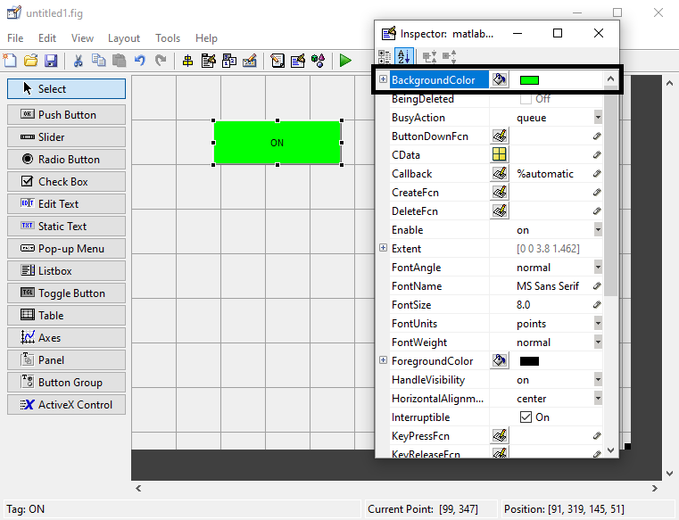
After changing the button name change the background color. (Note: This step is optional and you can skip it if you don’t want to change the background color)
Place 16 pushbuttons and make the above changes in the inspector window. For naming the Relays the static text option located in the left bar is used. The final look of my GUI is shown below:
After making the GUI open GUI Code that is created at the backend and make some alterations in the code that are stated as under.
Step 7: MATLAB Code of GUI:
function varargout = final(varargin)

% FINAL MATLAB code for final.fig

%      FINAL, by itself, creates a new FINAL or raises the existing

%      singleton*.

%

%      H = FINAL returns the handle to a new FINAL or the handle to

%      the existing singleton*.

%

%      FINAL('CALLBACK',hObject,eventData,handles,...) calls the local

%      function named CALLBACK in FINAL.M with the given input arguments.

%

%      FINAL('Property','Value',...) creates a new FINAL or raises the

%      existing singleton*.  Starting from the left, property value pairs are

%      applied to the GUI before final_OpeningFcn gets called.  An

%      unrecognized property name or invalid value makes property application

%      stop.  All inputs are passed to final_OpeningFcn via varargin.

%

%      *See GUI Options on GUIDE's Tools menu.  Choose "GUI allows only one

%      instance to run (singleton)".

%

% See also: GUIDE, GUIDATA, GUIHANDLES

% Edit the above text to modify the response to help final

% Last Modified by GUIDE v2.5 25-Aug-2019 13:10:11

% Begin initialization code - DO NOT EDIT

gui_Singleton = 1;

gui_State = struct('gui_Name',       mfilename, ...

                   'gui_Singleton',  gui_Singleton, ...

                   'gui_OpeningFcn', @final_OpeningFcn, ...

                   'gui_OutputFcn',  @final_OutputFcn, ...

                   'gui_LayoutFcn',  [] , ...

                   'gui_Callback',   []);

if nargin && ischar(varargin{1})

    gui_State.gui_Callback = str2func(varargin{1});

end

if nargout

    [varargout{1:nargout}] = gui_mainfcn(gui_State, varargin{:});

else

    gui_mainfcn(gui_State, varargin{:});

end

% End initialization code - DO NOT EDIT

% --- Executes just before final is made visible.

function final_OpeningFcn(hObject, eventdata, handles, varargin)

% This function has no output args, see OutputFcn.

% hObject    handle to figure

% eventdata  reserved - to be defined in a future version of MATLAB

% handles    structure with handles and user data (see GUIDATA)

% varargin   command line arguments to final (see VARARGIN)

% Choose default command line output for final

handles.output = hObject;

% Update handles structure

guidata(hObject, handles);

% UIWAIT makes final wait for user response (see UIRESUME)

% uiwait(handles.figure1);

% --- Outputs from this function are returned to the command line.

function varargout = final_OutputFcn(hObject, eventdata, handles)

% varargout  cell array for returning output args (see VARARGOUT);

% hObject    handle to figure

% eventdata  reserved - to be defined in a future version of MATLAB

% handles    structure with handles and user data (see GUIDATA)

% Get default command line output from handles structure

varargout{1} = handles.output;

clear all;

global a;

a = arduino;

% --- Executes on button press in pushbutton1.

function pushbutton1_Callback(hObject, eventdata, handles)

% hObject    handle to pushbutton1 (see GCBO)

% eventdata  reserved - to be defined in a future version of MATLAB

% handles    structure with handles and user data (see GUIDATA)

global a;

writeDigitalPin(a,'D6',0);

% --- Executes on button press in pushbutton2.

function pushbutton2_Callback(hObject, eventdata, handles)

% hObject    handle to pushbutton2 (see GCBO)

% eventdata  reserved - to be defined in a future version of MATLAB

% handles    structure with handles and user data (see GUIDATA)

global a;

writeDigitalPin(a,'D6',1);

% --- Executes on button press in pushbutton3.

function pushbutton3_Callback(hObject, eventdata, handles)

% hObject    handle to pushbutton3 (see GCBO)

% eventdata  reserved - to be defined in a future version of MATLAB

% handles    structure with handles and user data (see GUIDATA)

global a;

writeDigitalPin(a,'D7',0);

% --- Executes on button press in pushbutton4.

function pushbutton4_Callback(hObject, eventdata, handles)

% hObject    handle to pushbutton4 (see GCBO)

% eventdata  reserved - to be defined in a future version of MATLAB

% handles    structure with handles and user data (see GUIDATA)

global a;

writeDigitalPin(a,'D7',1);\

% --- Executes on button press in pushbutton5.

function pushbutton5_Callback(hObject, eventdata, handles)

% hObject    handle to pushbutton5 (see GCBO)

% eventdata  reserved - to be defined in a future version of MATLAB

% handles    structure with handles and user data (see GUIDATA)

global a;

writeDigitalPin(a,'D8',0);

% --- Executes on button press in pushbutton6.

function pushbutton6_Callback(hObject, eventdata, handles)

% hObject    handle to pushbutton6 (see GCBO)

% eventdata  reserved - to be defined in a future version of MATLAB

% handles    structure with handles and user data (see GUIDATA)

global a;

writeDigitalPin(a,'D8',1);

% --- Executes on button press in pushbutton7.

function pushbutton7_Callback(hObject, eventdata, handles)

% hObject    handle to pushbutton7 (see GCBO)

% eventdata  reserved - to be defined in a future version of MATLAB

% handles    structure with handles and user data (see GUIDATA)

global a;

writeDigitalPin(a,'D9',0);

% --- Executes on button press in pushbutton8.

function pushbutton8_Callback(hObject, eventdata, handles)

% hObject    handle to pushbutton8 (see GCBO)

% eventdata  reserved - to be defined in a future version of MATLAB

% handles    structure with handles and user data (see GUIDATA)

global a;

writeDigitalPin(a,'D9',1);

% --- Executes on button press in pushbutton9.

function pushbutton9_Callback(hObject, eventdata, handles)

% hObject    handle to pushbutton9 (see GCBO)

% eventdata  reserved - to be defined in a future version of MATLAB

% handles    structure with handles and user data (see GUIDATA)

global a;

writeDigitalPin(a,'D10',0);

% --- Executes on button press in pushbutton10.

function pushbutton10_Callback(hObject, eventdata, handles)

% hObject    handle to pushbutton10 (see GCBO)

% eventdata  reserved - to be defined in a future version of MATLAB

% handles    structure with handles and user data (see GUIDATA)

global a;

writeDigitalPin(a,'D10',1);

% --- Executes on button press in pushbutton11.

function pushbutton11_Callback(hObject, eventdata, handles)

% hObject    handle to pushbutton11 (see GCBO)

% eventdata  reserved - to be defined in a future version of MATLAB

% handles    structure with handles and user data (see GUIDATA)

global a;

writeDigitalPin(a,'D11',0);

% --- Executes on button press in pushbutton12.

function pushbutton12_Callback(hObject, eventdata, handles)

% hObject    handle to pushbutton12 (see GCBO)

% eventdata  reserved - to be defined in a future version of MATLAB

% handles    structure with handles and user data (see GUIDATA)

global a;

writeDigitalPin(a,'D11',1);

% --- Executes on button press in pushbutton13.

function pushbutton13_Callback(hObject, eventdata, handles)

% hObject    handle to pushbutton13 (see GCBO)

% eventdata  reserved - to be defined in a future version of MATLAB

% handles    structure with handles and user data (see GUIDATA)

global a;

writeDigitalPin(a,'D12',0);

% --- Executes on button press in pushbutton14.

function pushbutton14_Callback(hObject, eventdata, handles)

% hObject    handle to pushbutton14 (see GCBO)

% eventdata  reserved - to be defined in a future version of MATLAB

% handles    structure with handles and user data (see GUIDATA)

global a;

writeDigitalPin(a,'D12',1);

% --- Executes on button press in pushbutton15.

function pushbutton15_Callback(hObject, eventdata, handles)

% hObject    handle to pushbutton15 (see GCBO)

% eventdata  reserved - to be defined in a future version of MATLAB

% handles    structure with handles and user data (see GUIDATA)

global a;

writeDigitalPin(a,'D13',0);

% --- Executes on button press in pushbutton16.

function pushbutton16_Callback(hObject, eventdata, handles)

% hObject    handle to pushbutton16 (see GCBO)

% eventdata  reserved - to be defined in a future version of MATLAB

% handles    structure with handles and user data (see GUIDATA)

global a;

writeDigitalPin(a,'D13',1);
The m-file along with the GUI Code can be downloaded from Here.
Step 8: Code Explanation
When we create the MATLAB GUI code is automatically generated at the backend and we just need to do some alterations in the Code. There are a total of 16 functions in the code. Eight are for turning ON the relays and eight are for turning OFF the relays. Firstly, we created a global variable named ‘a’ is declared outside the functions and then it is used in every condition because it is useful when multiple functions are accessing the same data. Then we wrote a=arduino in the Code because we are interfacing the Arduino with MATLAB. All of the 16 functions which are designed for pushbuttons in the Code were modified and we wrote ‘0’ for turning OFF the relay and ‘1’ for turning ON the relay in those functions. You will have to add these two lines at the end of every function and modify them accordingly:
global a;

 writeDigitalPin(a,'D13',1);
Step 9: Assembling The Hardware
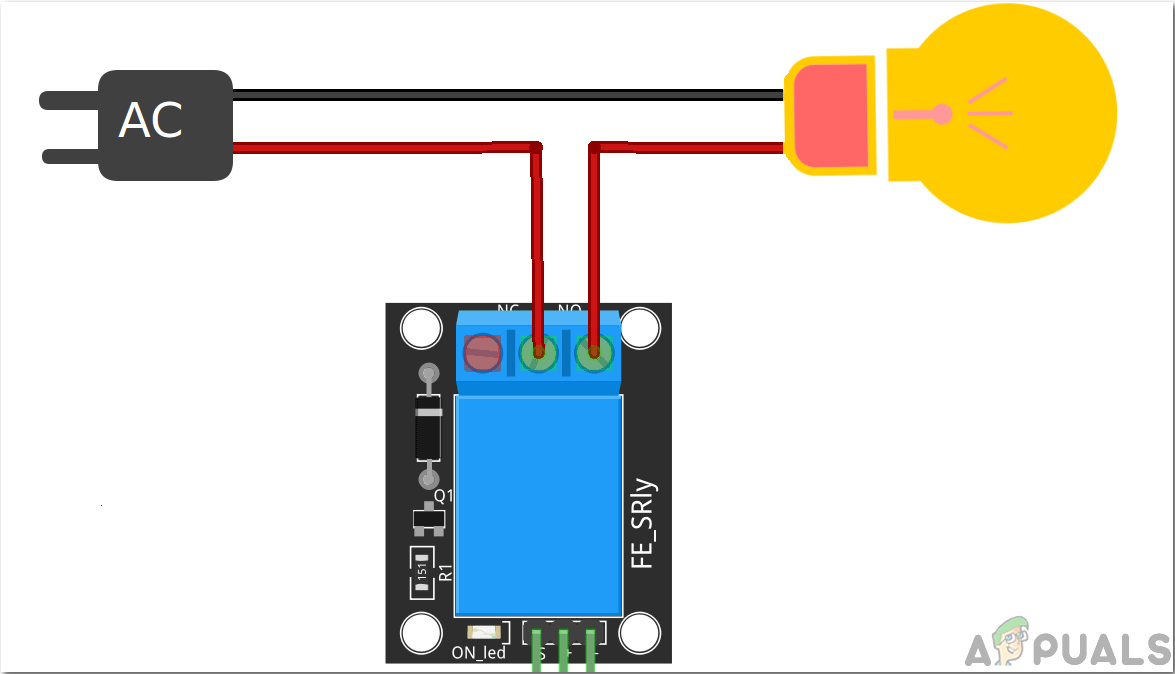
After writing the Code we will start assembling the hardware components. Firstly, we need to know the relay module connectivity. Take the positive wire of the appliance and cut it. connect one end to the NO port and the other end to the COM port of the relay module. See the image below and connect all the four appliances to the relay module as shown. Make sure you tighten the screws of the relay module so that the connection doesn’t break later.
After connecting the NO and COM pins of the eight relay modules with eight appliances we will connect the OUT pins of the module. Pin no 6-13 of Arduino are used for connecting the OUT pins of the relay module. Plug the OUT pin of Relay 1 to the pin 6 of Arduino and then do all the connections according to the Code. Use breadboard to make common connections of Vcc and Ground and then put the wires of these two pins of the Relay module in those connections. After making Relay connections connect the Vcc and Ground of the RS232 to the 5V and Ground of the Arduino respectively. Connect the Tx pin of the RS232 to the RX pin of the Arduino and connect the Rx pin of the RS232 to the Tx pin of Arduino. Take the Serial DB9 male adapter and connect it’s one side to the Serial Port converter module and the other side to the laptop or PC that you are using.
That’s it! We have completed our automation project and now we can control our appliances by using MATLAB. There is no need to get up and turn ON the appliances we can turn them ON and OFF remotely. It can be implemented in homes and as well as offices etc.


