How To Interface Arduino With MATLAB?
The microcontrollers are used in several electronic projects and they have immense importance in the field of electronics. The microcontroller named Arduino is used in almost every electronics project and it is used to carry out various operations in different circuits. We burn a C Code on this board to tell it how and what operations to perform. In this article, we will learn the interfacing of the Arduino with MATLAB. MATLAB is a software that includes several built-in engineering algorithms, plotting functions, and Hardware Packages. Projects like Automation Systems can be operated through MATLAB but to do so, firstly we have to install some Hardware Support Packages in MATLAB. Communication of Arduino with MATLAB requires just a USB cable. In this article, we will install certain packages and then we will run some basic tests to confirm that we have achieved our goal.
How To Communicate To The Arduino Board Through A USB Cable?
As we know the abstract of the project we will start downloading the software needed and collecting some hardware components for testing. We will use Arduino UNO for interfacing and then later for testing.
Step 1: Components Used (Hardware)
- No products found.
- 1k Ohm Resistor
- LED's
- Breadboard Jumper Wires
- No products found.
Step 2: Components Used (Software)
After arranging the hardware components we will look for the software that will be used in the project. We will install the latest version of MATLAB on our laptop or PC on which we are working. It is better to download MATLAB 2019 because it is the latest release from Mathworks. The link to the official website of Mathworks is available below for downloading the software.
Step 3: Installing Hardware Support Packages
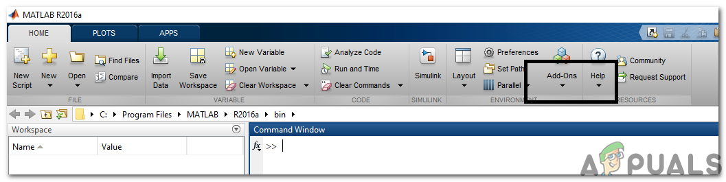
- Start MATLAB.

MATLAB 2019 - Look for Add-Ons Tab in the Home menu and then click on that.
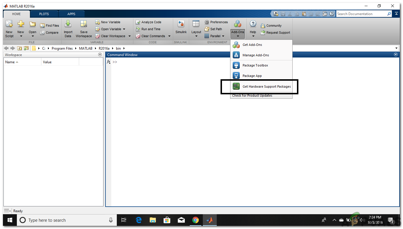
Clicking Add-Ons - A drop-down menu will appear and from that menu select “Get Hardware Support Packages“.
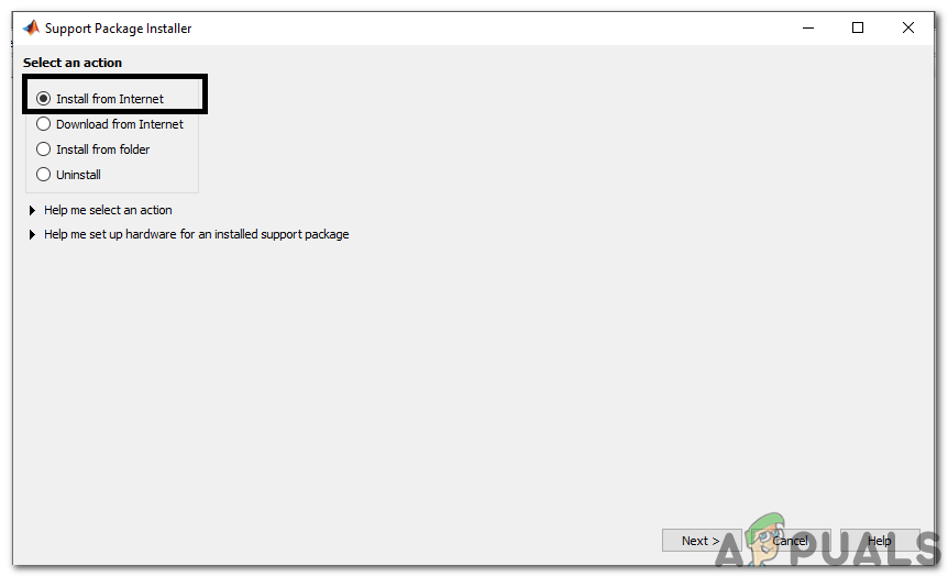
Looking For Hardware Packages - Support Package Installer will open and select Install from the Internet.
Installing the Packages - The next window will appear which will show all the available packages of MATLAB. Look for the Arduino package in the list and then click next to continue the installation. The picture below shows that the packages are already installed because I have already installed them before. Note: Check-in both packages named as Simulink and MATLAB.
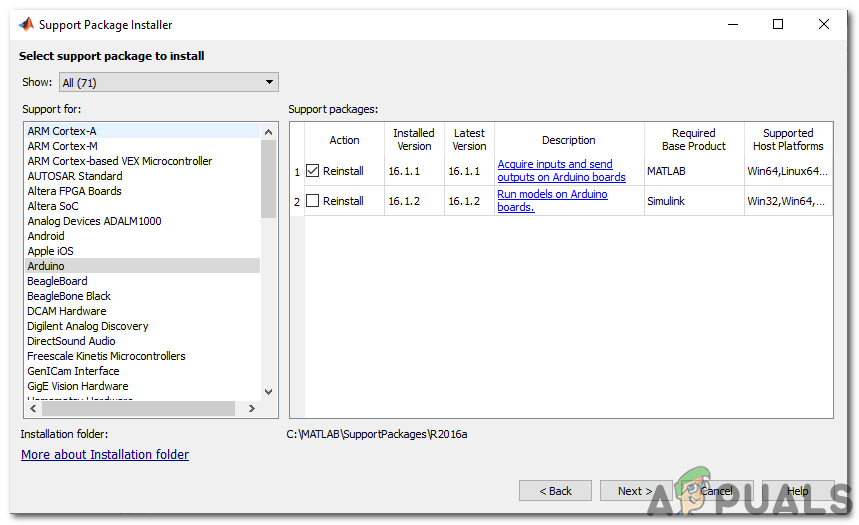
Packages Found
After clicking next a window will open asking for Login details of Mathworks Account. If you don’t have one please make an account and then proceed further. As I have already entered the Login details, the packages will be installed and now we are ready to do the testing.
Step 4: Verifying The Hardware Packages Installed
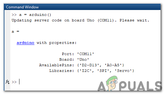
We have completed the installation of packages hence we will check whether they are appearing in MATLAB also. For that we will type the following command in the command window:
a=arduino()
Sometimes, there is more than one microcontroller connected to the PC so, we have to tell that which board are we talking to. For checking the port number we will go the Control Panel then Devices and Printers and check the COM port number:
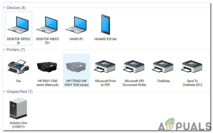
Now, we become to know that our Arduino is connected to COM11 so we will mention that port number in the Code. In my case the Port number is COM11 and it will be different in everyone’s PC so, change the port number in the code before compiling it :
a = arduino(‘com11’, ‘uno’)
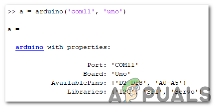
MATLAB will try to communicate with the Arduino Board and if the communication is successful some properties like the Port number, Model of the Board etc will be displayed on the screen.
The variable named ‘a’ will be appearing in the workspace, and the following command will be used to clear the variable a.
clear a
Step 5: Testing
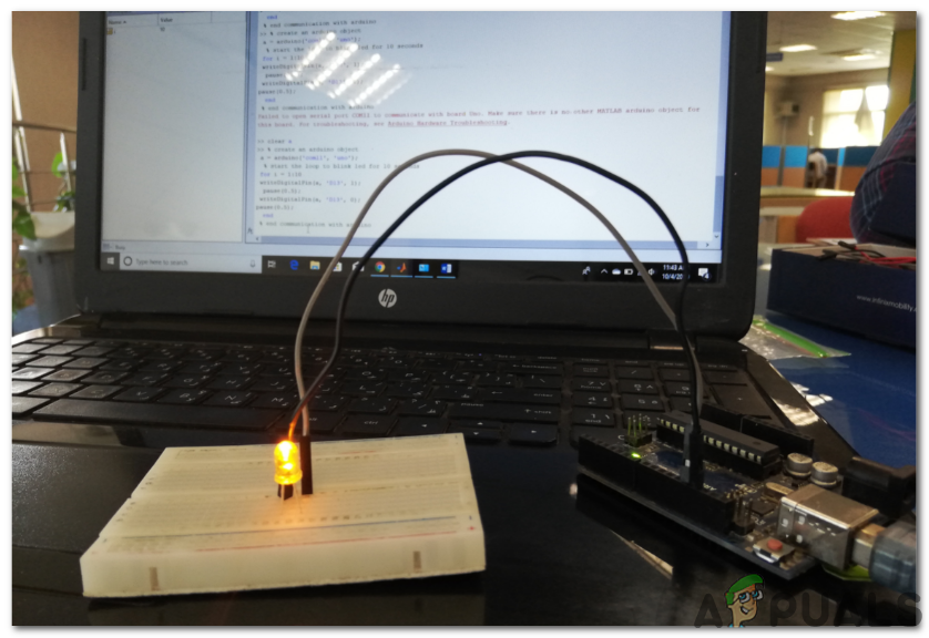
We will do the LED blink test on Arduino using MATLAB. As we have connected the Arduino board with a laptop or PC by a USB Cable and verified that the packages are installed now we do perform an LED blink test to check whether our hardware and software are working properly. There are two portions of the testing part.
- Wiring The Circuit: Connect the circuit according to the diagram shown below. Connect the positive pin of the LED to pin number 13 of the Arduino and connect the ground of the LED to the Ground of the Arduino next to pin number 13. Connect a 1k Ohm Resistor with the negative leg of the LED so that the LED doesn’t blow when power is turned ON. (Note: Adding the resistor in the circuit is not compulsory because the Voltage is not as much to blow off the LED.)
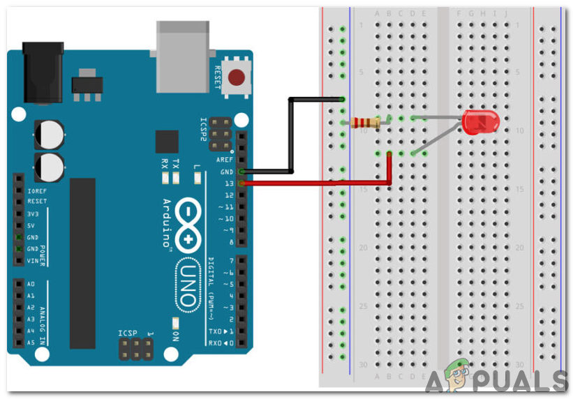
Circuit Diagram - CODE: After assembling the circuit on the hardware open MATLAB software and write the following code on it. The code is very simple and self-explanatory, but some general explanation of the code is given below:
% create an arduino object

 a = arduino('com11', 'uno');

 % start the loop to blink led for 10 seconds

 for i = 1:10

writeDigitalPin(a, 'D13', 1);

 pause(0.5);

writeDigitalPin(a, 'D13', 0);

pause(0.5);

 end

 % end communication with arduino

clear a
Download the MATLAB Code from Here
Ensure there is no past Arduino variable stored in MATLAB, otherwise, MATLAB will show an error message. Save the m-file and then Run the Code. It will be seen that the LED blinks for a period of one second and then turn OFF. That’s it! We have finally interfaced with the Arduino UNO Board with MATLAB and now we can make some cool electronics projects using Arduino microcontroller and then control them using MATLAB.


