DIY: Control Your Water Geyser Temperature From Your Smartphone
Pouring hot water onto your skin can result in skin burn and in most cases, a person can be scalded when he/she runs that boiling water. Hence, there is a need for controlling the water temperature of the geysers that are installed at our homes; not only for the betterment of our health but our safety too. The interface for setting the temperature on a water geyser will vary by its type and manufacturing model. Luckily, most water geyser types are adjusted similarly. Today, we will design a prototype and make some changes to the water geyser installed at the home so that we are able to control the temperature wirelessly. Now, without wasting a second let’s get to work.
How To Setup Controller Unit Next To Your Water Geyser?
The geysers remain ON for long intervals and the water keeps on boiling inside them which results in wastage of electricity. If the temperature is set too low then the hot water will feel like mild-warm and it can also lead to bacterial growth. Hence, we will design a controller that will be responsible for maintaining a reasonable temperature in the geyser. Firstly, we will make a list of the hardware components needed to design the system.
Step 1: Components Needed
- No products found.
- No products found.
- Wired Mouse
- HDMI To VGA Connector
Step 3: Working Principle Of The Project
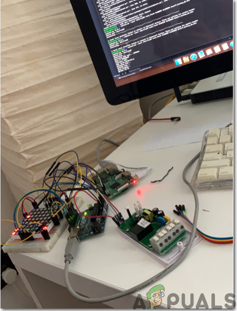
There will be a controller circuit that would reside next to the water geyser that is present on the ground floor and it would be connected with the geyser. The circuit will be split into two portions. The main circuit will be the controller circuit and the rest of the circuits are secondary circuits and they can be decided on the number of geysers that are present in the house. All of those circuits would be connected with each other through an internet connection. The main circuit will comprise of a Raspberry Pi 3B+ and a Relay module. The main circuit will be responsible for maintaining the desired temperature at the ground floor’s geyser. The secondary circuits will comprise a temperature sensor, resistor, and raspberry pi. To make this project economical you can use Raspberry Pi zero while assembling the secondary circuits.
Step 4: Setting Up Raspberry Pi
There are two options for setting up Raspberry Pi. First, one is to connect your Pi with LCD and connect all the necessary peripherals and start working. The second one is to set up Pi with the laptop and access it remotely. It depends on the availability of LCD, if you have it at home then you can set up your Pi by using an LCD. Connect the LCD to the HDMI port of the Raspberry by using HDMI to VGA adapter. If you want to access your Pi remotely follow my article named “How To Access Graphical User Interface (GUI) Of Raspberry Pi Using SSH And VNC Viewer?“. In this article, a detailed setup of Pi with a laptop is described and after logging in you would be able to gain the remote access to Pi.
Step 5: Make Sure That Raspberry Pi Is Up To Date
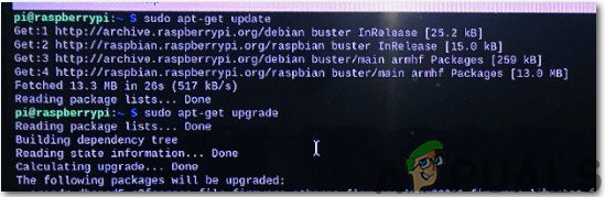
After setting up Raspberry Pi we would ensure that our Pi is working fine and all the latest packages are installed on it. Open the Command Window and type the following two commands to update Pi.
sudo apt-get update
Then,
sudo apt-get upgrade
If any updates are installed, press Y and then press Enter to continue downloading updates.
Step 6: Configuring Static IP’s And Hostnames For Pi Zero And 3B+
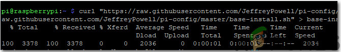
Now, we need to configure the static IP addresses for Raspberry Pi Zero that will be placed near to the other geysers available in the house. Before configuring IP’s enable one wire from Raspberry Pi configuration. Run the following command to configure static IP’s:
curl "https://raw.githubusercontent.com/JeffreyPowell/pi-config/master/base-install.sh" > base-install.sh && sudo bash base-install.sh
In my case, the IP’s assigned to the circuits are stated below. These will be different in your case. After configuring the static IP’s change the hostnames. You can name them like Controller, geyser 1, etc.
Controller: 192.168.1.15 (Ground Floor)
Geyser 1: 192.168.1.16 (First Floor)
Geyser 2: 192.168.1.17 (First Floor)
Now, reboot your Pi.
Step 7: Assembling Controller Circuit.
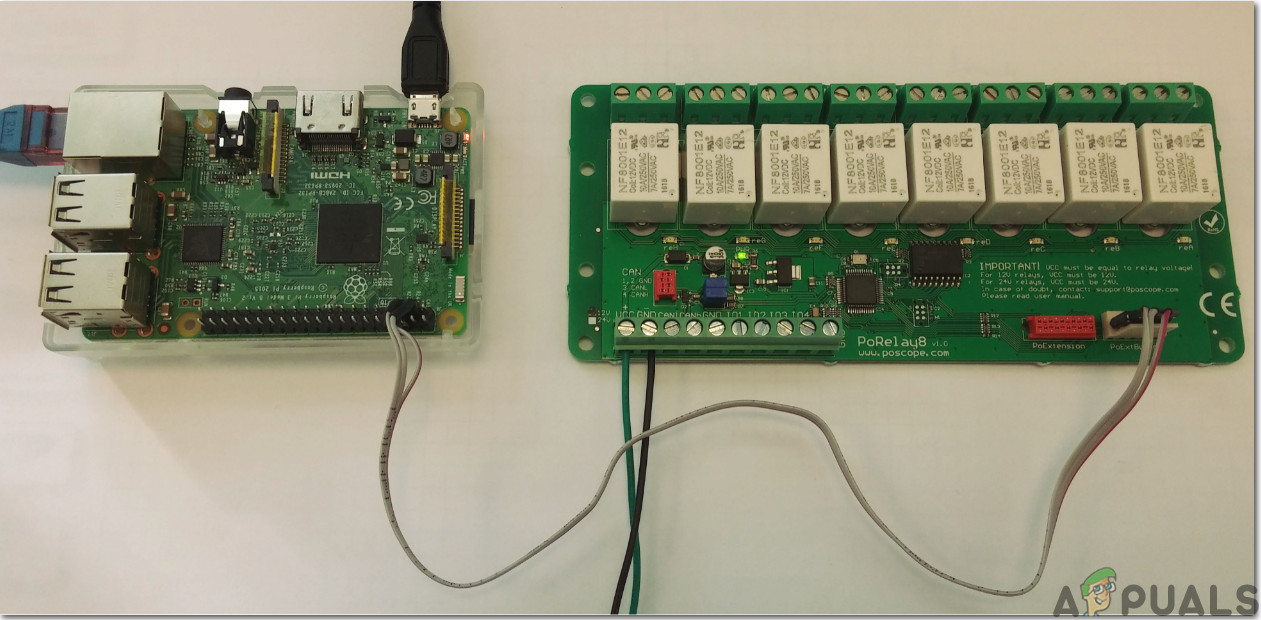
Before assembling the circuit check the pin configuration of Raspberry Pi 3B+ and point out the GPIO pins. The 5V and GND pins of the relay module will be connected to the 5V and GND pins of the Raspberry Pi. Then the GPIO pin 14 will be connected to the relay of a water geyser and the GPIO pin 15 will be connected to the relay module that is connected with Pi. Now, we need to check the wiring diagram of our water geyser. After referring to the wiring diagram. My geyser uses a 25min/24hr clock and a thermostat that is remote wired. The warming is constrained by the clock and indoor regulator, the heated water evaporator is continually on and water temperature is controlled by means of the boiler thermostat.
Now, connect the heating relay with the timer and thermostat and you will observe that when the old thermostat is turned to maximum and the clock is turned on the relay module will control the heating pump.
Step 8: Making Software Changes For Controlling The Circuit
After assembling the main hardware we will make some software changes to control it remotely. Some packages like MySQL will be installed that would be responsible for controlling the relays and maintaining the record of temperatures. Open the terminal of Raspberry Pi and execute the following command:
curl "https://raw.githubusercontent.com/JeffreyPowell/pi-config/master/pi-heating-hub-install.sh" > pi-heating-hub-install.sh && sudo bash pi-heating-hub-install.sh
After running this command, you would be asked to enter the root password. The root password is the default password that is used for the initial login. The database needs to be configured now:
curl "https://raw.githubusercontent.com/JeffreyPowell/pi-config/master/pi-heating-hub-mysql-setup.sh" > pi-heating-hub-mysql-setup.sh && sudo bash pi-heating-hub-mysql-setup.sh
Now, browse the following command:
http://192.168.1.15:8080/status.php
The status page will be displayed and there will be no data because the sensors are not set up yet.
Step 9: Configuring The Secondary Circuits
Before configuring the secondary circuits we need to understand the pin configuration of the DHT11 sensor. It is also displayed below for your ease:
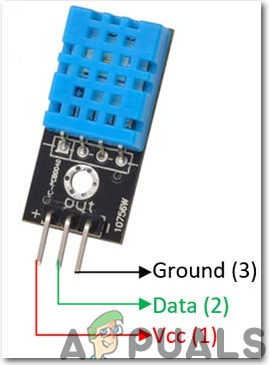
Connect the Vcc and GND pin of DHT11 to the 3.3V and GND pin of Raspberry Pi Zero and the data pin to the GPIO 4 pin of the Pi. Female to female jumper wires would be required for wiring these connections. In my case, there are three geysers in the house so for secondary connections two raspberry pi zero’s are needed. It may differ in your case.
Step 10: Making Software Changes For Secondary Circuits
Some software changes need to be made for controlling the geysers that are installed on the first floor. Hence, write a script for installing necessary packages:
curl "https://raw.githubusercontent.com/JeffreyPowell/pi-config/master/pi-heating-remote-install.sh" > pi-heating-remote-install.sh && sudo bash pi-heating-remote-install.sh

Then, reboot the Pi and after rebooting we need to know the unique serial numbers of sensors that are connected. Paste the following command in your terminal for doing so:
ll /sys/bus/w1/devices/
The unique serial numbers are 28-0000056e625e and 28-0000056ead51 respectively. Edit the config file and insert these serial numbers into it. For editing copy, the command written below:
vi home/pi/pi-heating-remote/configs/sensors
Erase the default settings and paste the serial number and a name for every sensor like this:
- 28-0000056e625e = Geyser1
- 28-0000056ead51 = Geyser2
Now, save and close the config file.
Step 11: Connecting Sensors And Relays With Each Other
As we have connected all of the hardware physically now we will connect it virtually too by means of wireless connection and then we would test it.
Open the browser from your mobile phone or laptop and type the following command:
http://192.168.1.15:8080/status.php
A webpage will open and on that page click on the Input Sensor button and then click on ‘Scan For New Sensors’. You will observe that the application would start searching for secondary circuits that you’ve set up before. The controller will update the geyser 1 and geyser 2 data and switching of relay takes place every minute. Click on Done and return to the main webpage.
Now, we will configure the relays for switching. Click on the Output Devices and then click on ‘Add New Button’ and after that click ‘Edit’ next to the new device button. Change the name to ‘Heat’ and enter the pin number 10 i.e. GPIO 15 or Raspberry Pi 3B+. In my case, the relays are active high so I will enter 1 in the Pin Active High/Low field. Save and return to the homepage. We’re almost done and just a schedule needs to be created to switch the relays ON and OFF.
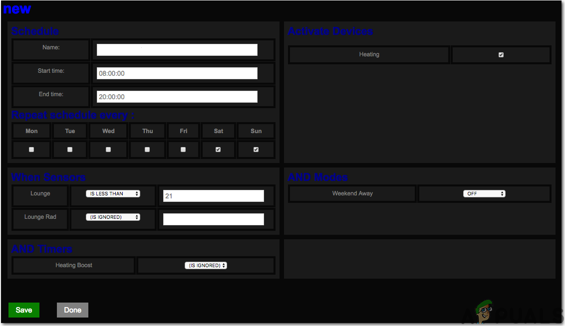
Step 12: Creating A Heating Schedule
A timetable can be activated at a particular time, a day of the week when the geysers are associated with the home Wifi. We can set modes in which flags are set that are either ON or OFF. In this mode, the relay will simply turn on or off depending on the instruction given. We can also set the timers in which the relay will be turned OFF after a specific time. The modes can be activated by navigating to the web page and clicking on modes followed by Add Activity and then editing those buttons. Similarly, timers can also be set by navigating to the web page. Simply click on Timers and change the duration of your choice. After saving return to the homepage and click the mode button on and off, and the timer button will count down every minute.
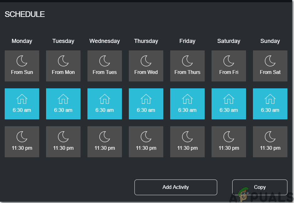
Step 13: Configuring Schedules
Navigate to the main homepage and click on Schedules and Add New. Rename the scedules, for example, you can name the schedules like ‘Morning Heating’ etc and then set the temperatures at which you want your geyser to be turned on like 25 degrees. Save the changes and exit.
That’s it! We are all set to control our water geyser remotely without any hassles. Keep visiting our website for more interesting projects in the future.


