How To Make Automated Washroom Light Switch Circuit?
In the current century, automation is seen to be implemented in almost everything. Automation systems are being installed in offices, homes, shops, markets, workplaces, etc. In this race of technology, an individual ought to choose the most recent automation systems to make their life simpler. Typically in our homes, we turn ON and OFF the lights physically. How good it will be if the lights turn on or off at the moment when u open or close a door.
In this project, I will tell you the best way to plan and manufacture a straightforward Automatic Washroom Light Switch Circuit, which will consequently turn on lights when you enter the washroom and turns it off when you leave. Via mechanizing this process, there are numerous advantages like, the individual need not think about switching off the light on or at whatever point he/she is utilizing the washroom. The circuit, which you will know about in a moment, does it automatically for that individual. The circuit is additionally intended to expend lesser power so the circuit can be utilized in any family unit or open washrooms without agonizing over the power bill.
How To Automate Washroom Lights?
We turn on the lights in our washroom when we enter it and turn them off when we leave. sometimes, we forget to switch off the lights after leaving the washroom. This may prompt power wastage and furthermore the lifetime of the lights may diminish. To maintain a strategic distance from these issues, I will tell you the best way to make a straightforward circuit which will consequently turn the lights on when an individual enters the washroom and it automatically turns it off when he/she leaves it.
Step 1: Collecting The Components
If you want to avoid any inconvenience in the middle of any project, the best approach is to make a complete list of all the components that we are going to use. The second step, before starting to make the circuit, is to go through a brief study of all these components. A list of all the components that we need in this project is given below.
- No products found.
- No products found.
- No products found.
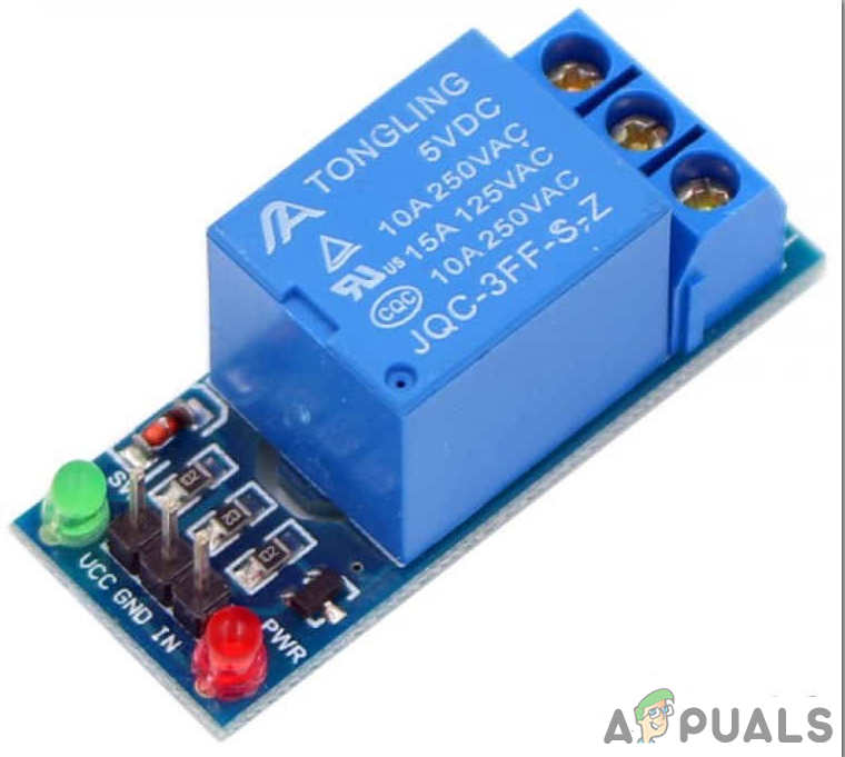
- 5V Relay Module
- BC558 PNP Transistor
- No products found.
- 100 ohm Resistor
- No products found.
- Connecting wires
- No products found.
- Battery
- No products found.
Step 2: Studying The Components
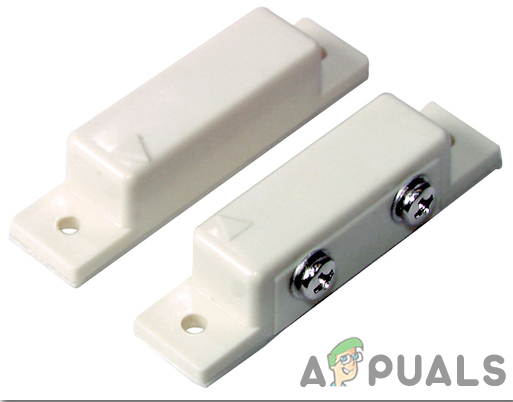
A Reed Switch is an electronic switch that functions because of the applied magnetic field. A pair of ferromagnetic flexible meta reeds contacts are used to construct the reed switch. These meta reeds contacts are closed in a hermetically sealed glass envelope. The contacts are usually normally open when a magnetic field is applied the contacts go to closed condition or it can be another way around. typically nickel-copper alloy is used to make these contacts because they are very easy to magnetize. Most of the reed switches have two ferromagnetic contacts. Some of them have only one ferromagnetic contact and the other is no-magnet. the function of a reed switch is the same as the function of a relay.
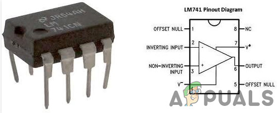
LM741 is an operational amplifier IC. Typically it can perform most of the analog operations. The voltage gain of this IC is very high, around 104 which allows it to operate in wide voltage ranges making it the most preferred operational amplifier. It is designed to perform many mathematical operations like addition, subtraction, multiplication, division, differentiation, etc by making a feedback circuit with the help of a resister or a capacitor. It is also used for amplification and comparing purposes. Short circuit protection and an internal frequency compensator circuit are also built in the IC. Its name 741 indicates that it has 7 functional pins from which 4 are input and 1 pin is for output. This op-amp comes with three form factors that are 8 Pin DIP Package, TO5-8 Metal can package, 8 Pin SOIC.
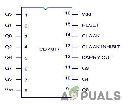
CD4017 is a CMOS Decade counter IC. Places where low range counting is to be done, this IC is used. It can cunt in the range of 0 to 10. Board space and time required to make the circuit both are reduced when this IC is used. The input supply voltage for this IC is from 3 to 15V. It is compatible with Transistor-Transistor Logic (TTL). The clock speed of this IC is 5MHz.This IC has a wide range of applications. It is used in automotive industries, manufacturing medical electronic devices, alarms, and electronic instrumentation devices.
A relay module is a switching device. It works in two modes, Normally Open (NO) and Normally Closed (NC). In NO mode, the circuit is always broken unless you send a HIGH signal to the relay through Arduino. NC mode works the other way around, The circuit is always complete unless you switch on the relay module. Make sure you connect the positive wire of your Electrical Appliance to the relay module in the way shown below.
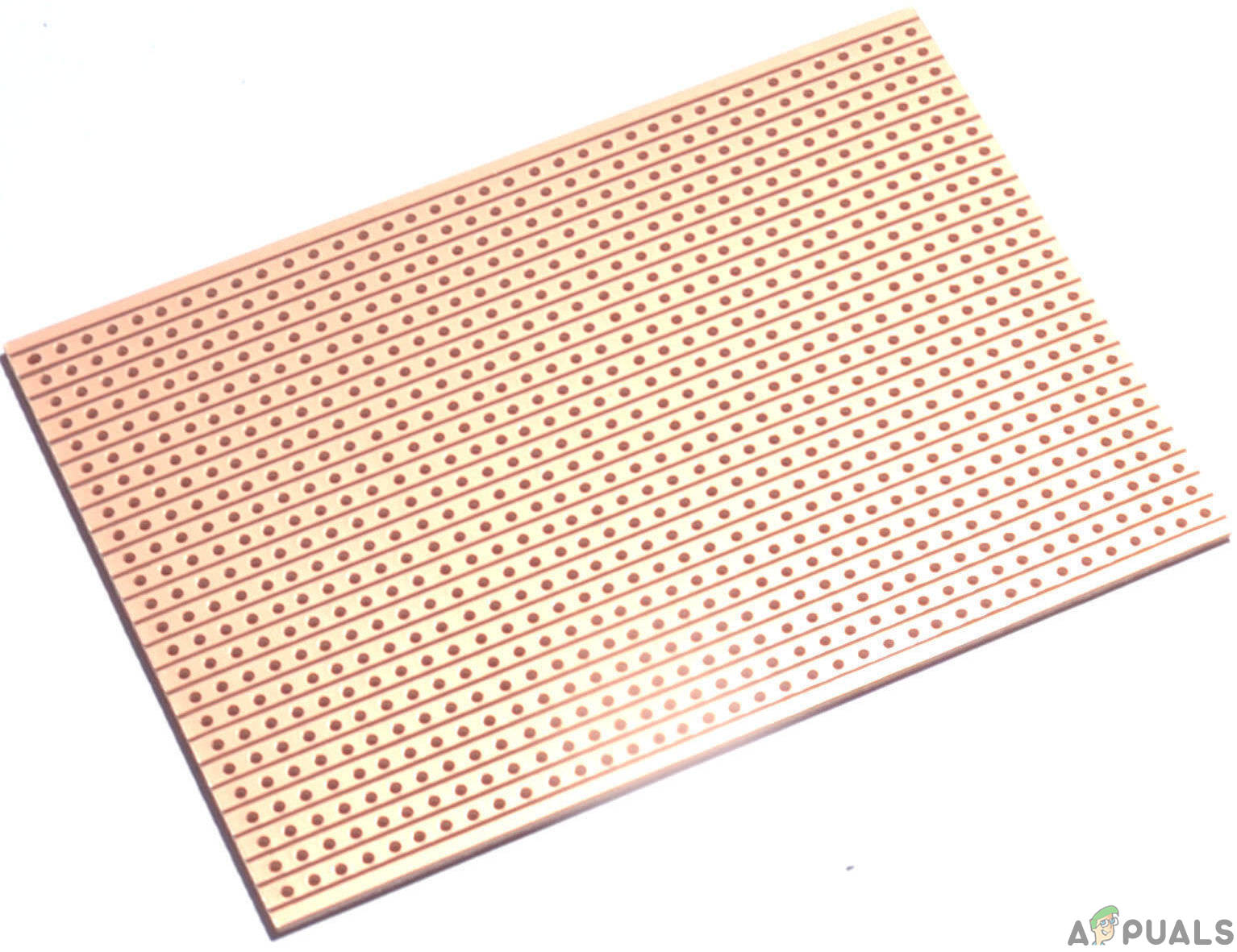
Veroboard is a good choice to make a circuit because the only headache is to place components on Vero-board and just solder them and check the continuity using the Digital Multi Meter. Once the circuit layout is known, cut the board into a reasonable size. For this purpose place the board on the cutting mat and by utilizing a sharp blade (securely) and by taking all the safety precautions, more than once score the load up top and base along the straight edge (5 or multiple times), running over the apertures. After doing so, place the components on the board closely to form a compact circuit and solder the pins according to the circuit connections. In case of any mistake, try to de-solder the connections and solder them again. Finally, check the continuity. Go through the following steps to make a good circuit on a Veroboard.
Step 3: Working of The Circuit
Before proceeding with the working of the circuit, I will initially clarify the expected arrangement of this circuit. The reed switch is fixed to the door at the entryway while the magnet is fixed to the entryway. This implies the reed switch will consistently be in a shut state as the door is shut when the washroom isn’t being used (which is accepted as a beginning stage) and the magnet will be close to the switch.
Suppose you opened the door and went into the washroom and after that shut the door behind you. This activity will do the switch open (when the door is opened first) and close (when you close the door).
Accordingly, the output of the Op-amp goes HIGH (when you open the door)and then goes LOW (when you close the door). This thus will make the counter produce a HIGH output at its Pin 2. Since Pin 2 of CD4017 is associated with relay, the light will be turned ON.
Presently, when you are finished with your business in the washroom, you will indeed open the door, leave the washroom and close the door. This activity will indeed cause a similar activity for example switch will open and close and output of Op-Amp will turn out to be HIGH and afterward LOW.
Be that as it may, since the Pin 4 of CD4017 is associated with the Reset pin, every one of the output will turn out to be LOW and henceforth the relay will turn OFF, which thus switches off the light.
Step 4: Assembling the Components
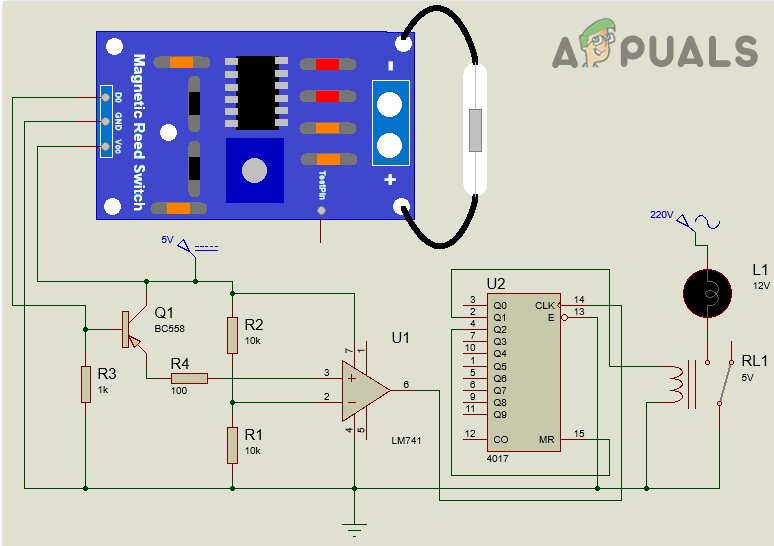
LM714 operational amplifier is the first most important component that is used in the circuit. It is being used in the comparator mode. Pin2 is the inverting pin of the operational amplifier and it is given input by two 10k-ohm resistors. The Reed switch is connected in such a way that its one pin is connected to a 5V supply and the other is connected to the base of a PNP transistor. A resistor is used to pull down the base of the transistor. The non-inverting pin of the op-amp is connected to the emitter of the transistor while the collector is connected to 5V. Pin1 of the LM741 is connected to the clock pin of the counter IC. Pin2 of the counter IC is connected to the relay and the pin15 is connected to pin4.
Now as we know the main connections and also the complete circuit of our project, let us move ahead and start making the hardware of our project. One thing must be kept n mind that the circuit must be compact and the components must be placed so close.
- Take a Veroboard and rub its side with the copper coating with a scraper paper.
- Now Place the components carefully and close enough so that the size of the circuit does not become very big
- Carefully make the connections using solder iron. If any mistake is made while making the connections, try to desolder the connection and solder the connection again properly, but in the end, the connection must be tight.
- Once all the connections are made, carry out a continuity test. In electronics, the continuity test is the checking of an electric circuit to check whether current flow in the desired path (that it is in certainty a total circuit). A continuity test is performed by setting a little voltage (wired in arrangement with a LED or commotion creating part, for example, a piezoelectric speaker) over the picked way.
- If the continuity test passes, it means that the circuit is adequately made as desired. It is now ready to be tested.
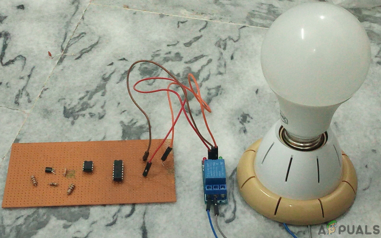
The circuit will look like the image below:
Step 5: Testing The Circuit
Go through the following steps to test your circuit.
- Power on the circuit after making the connections.
- Open the door of the washroom and enter it. Now close the door.
- The Light will be turned on.
- Now open the door again and get out of the washroom. Close the door again.
- The light will switch off.


