How To Make a Pickpocket Alarm Circuit?
Nowadays the biggest problem faced by the public in crowded areas is being pickpocketed. Some people are always waiting for you to come in crowded areas like markets, metro buses, metro trains, General stores, Bus stops, shopping malls or on the crowded footpaths. They slide things out of your pockets without you even knowing it. This may cause a great loss, you might lose some important documents, Credit Cards, money, etc that you keep in your wallets or purses and think it will be safe there.
This circuit mainly consists of a sound amplifier IC and a buzzer which are all connected. A pin is used to sound the buzzer. It is connected in such a way that if it is plugged in the circuit, the buzzer will not sound. If this pin is picked out of the circuit, the alarm will sound and the concerned person will be identified at the time he is being pickpocketed. The Pin will be tied on the inside of the pocket in which the wallet is placed and the circuit will be placed inside the wallet.
How To Make an Alarm To Prevent PickPockets?
This circuit encourages us to get alarmed when anyone picks our pockets or sacks. The circuit is exceptionally useful to alert our merchandise getting pick stashed. The circuit is known as a force stick security alert circuit since it gets enacted when the stick is pulled.
Step 1: Collecting The Components
The best approach to start any project is to make a complete list of components. This is not only an intelligent way to start a project but it also saves us from many inconveniences in the middle of the project. A list of components, which are very easily available in the market, is given below:
- No products found.
- No products found.
- No products found.
- Veroboard
- Solder Iron Set
- Connecting Wires
Step 2: Studying The Components
As now, we have a complete list of all the components, let us move a step ahead and go through a brief study of all the components.
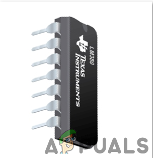
LM380 is an amplifier IC, specially designed to amplify the user’s audio signal. Its gain is normally fixed up to 34dB. In this amplifier IC, the output automatically maintains its level to half of the supplied input voltage. Several features of this amplifier include three ground pins, wide supply voltage range, low distortion, high peak voltage, etc. Other than Intercom circuits, it can be used in alarms, televisions, sound systems, and photograph amplifiers, etc.
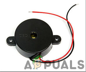
The buzzer is a sort of electronic sound collector with a coordinated structure. It is generally utilized as a voice gadget in electronic items like PCs, printers, replicating machines, alert mechanical assembly, electronic toys, auto electronic gadgets, phones, etc..In this project, we are going to utilize a buzzer to sound an alarm when the pin is picked out of the main circuit.
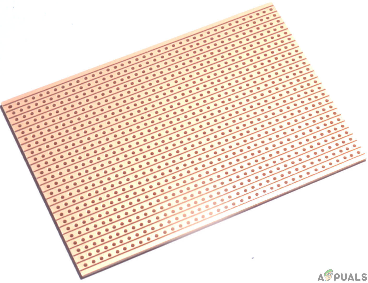
Veroboard is a good choice to make a circuit because the only headache is to place components on Vero-board and just solder them and check the continuity using the Digital Multi Meter. Once the circuit layout is known, cut the board into a reasonable size. For this purpose place the board on the cutting mat and by utilizing a sharp blade (securely) and by taking all the safety precautions, more than once score the load up top and base along the straight edge (5 or multiple times), running over the apertures. After doing so, place the components on the board closely to form a compact circuit and solder the pins according to the circuit connections. In case of any mistake, try to de-solder the connections and solder them again. Finally, check the continuity. Go through the following steps to make a good circuit on a Veroboard.
Step 3: Simulating The Circuit
Before making the circuit it is better to simulate and examine all the readings on a software. The software we are going to use is the Proteus Design Suite. Proteus is a software on which electronic circuits are simulated. First, the circuit is made and then it runs to take all the measurements.
To download the software, Click Here
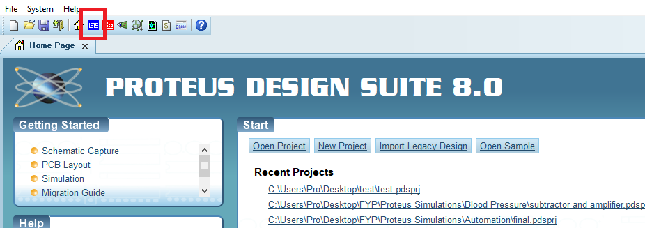
- After you download and install the Proteus software, open it. Open a new schematic by clicking the ISIS icon on the menu.
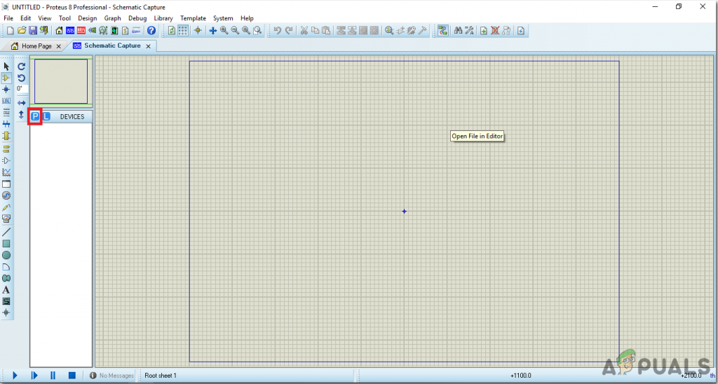
New Schematic. - When the new schematic appears, click on the P icon on the side menu. This will open a box in which you can select all the components that will be used.
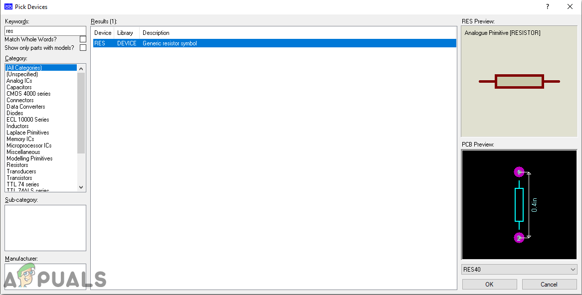
New Schematic - Now type the name of the components that will be used to make the circuit. The component will appear in a list on the right side.
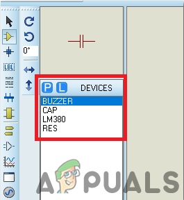
Selecting Components - In the same way, as above, search all the components. They will appear in the Devices List.
Component List - The Final Circuit will look like the image shown below:
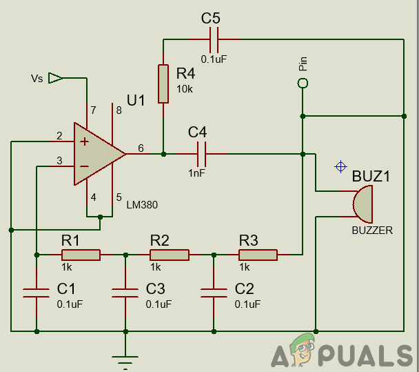
Circuit Diagram
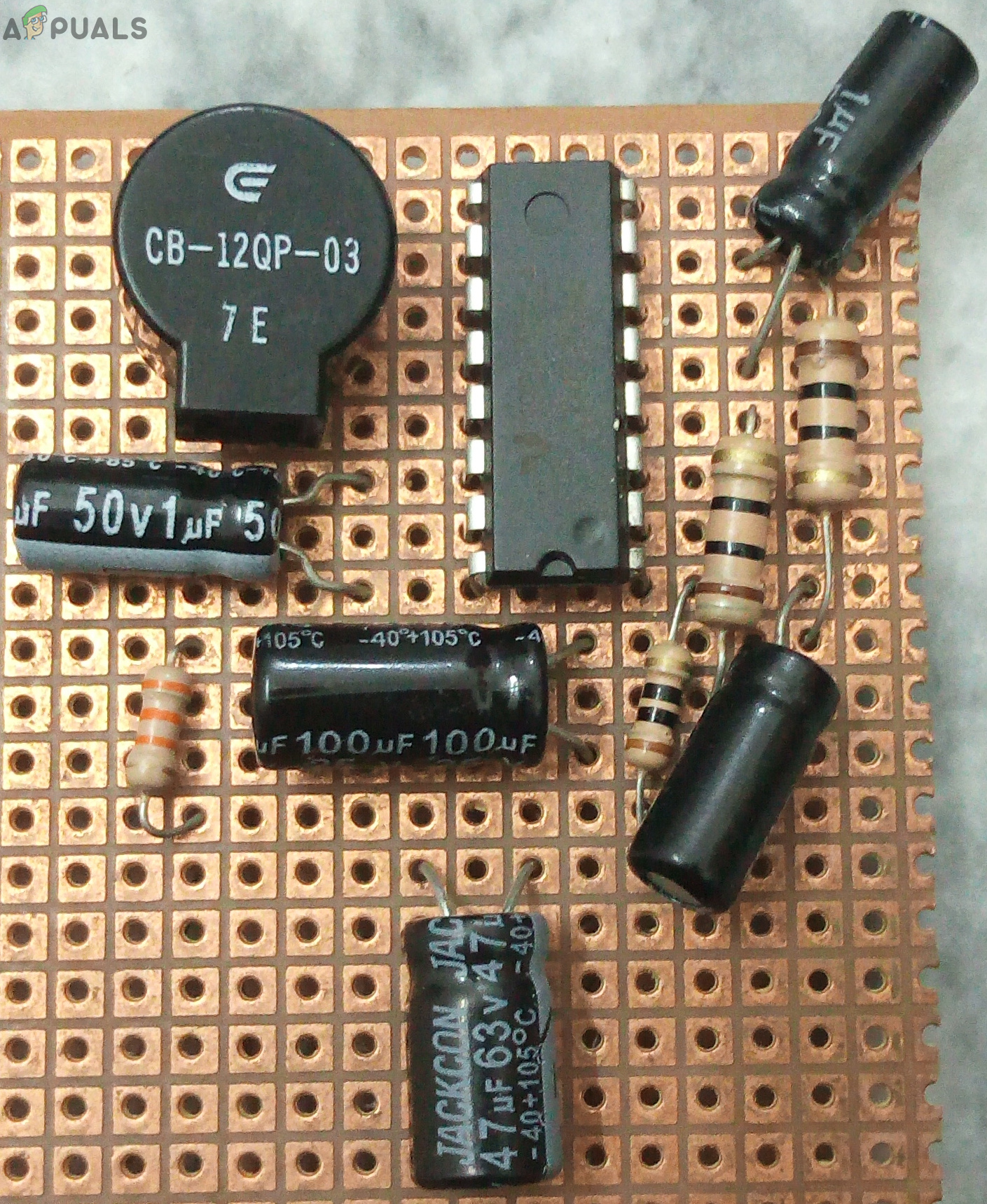
Step 4: Making The Hardware
Now as we know the main working and also the complete circuit of our project, let us move ahead and start making the hardware of our project. One thing must be kept n mind that the circuit must be compact and the components must be placed so close, that the full size of the circuit board can fit in your purse or wallet.
- Take a Veroboard and rub its side with the copper coating with a scraper paper.
- Now Place the components carefully and close enough so that the size of the whole circuit does not exceed the size of the wallet.
- Carefully make the connections using solder iron. If any mistake is made while making the connections, try to desolder the connection and solder the connection again properly, but in the end, the connection must be tight.
- Once all the connections are made, carry out a continuity test. In electronics, the continuity test is the checking of an electric circuit to check whether current flow in the desired path (that it is in certainty a total circuit). A continuity test is performed by setting a little voltage (wired in arrangement with a LED or commotion creating part, for example, a piezoelectric speaker) over the picked way.
- If the continuity test passes, it means that the circuit is properly made as desired. It is now ready to be tested.
Step 5: Testing The Circuit
Now, this is the final step in which we are going to test the circuit. Tie the pin on the circuit with a small thread and connect the other end of the thread with a clip or a hook that can stick to the inside cloth of the pocket, or the purse. When it is done, Put the circuit into your wallet so that the components don’t break. Attach the hook or the clip to the inside cloth of the pocket or the purse. Now take the thing, which has the circuit in it, out of your pocket or the purse. By doing so, the buzzer should start ringing. If it rings, it means that the circuit is working properly.
Now we know the whole procedure to make an anti-pickpocket alarm. You can start working right now to make your circuit and use it in your pockets or purses to prevent people from stealing important stuff from you.
Applications
This circuit is used as a pickpocket alarm here. But it also has a wide range of applications where it can be used to draw the attention of the people if any alarming situation occurs. Some of its applications are listed as follows.
- Car Door Alarm.
- Main Door Alarm at Homes.
- Anti-Theft Alarm.
- Preventing the removal of items.


