‘Design Arduino Based Home Automation System using TV remote’
Home Automation System is the fastest-growing concept of the modern world. Smart home automation is a concept in which a single device is used to control various electronic parameters of a house, for example, switching of home appliances, monitoring of security alarms, garage door automation, etc.
Design Guides: Best Computers For Graphics Design
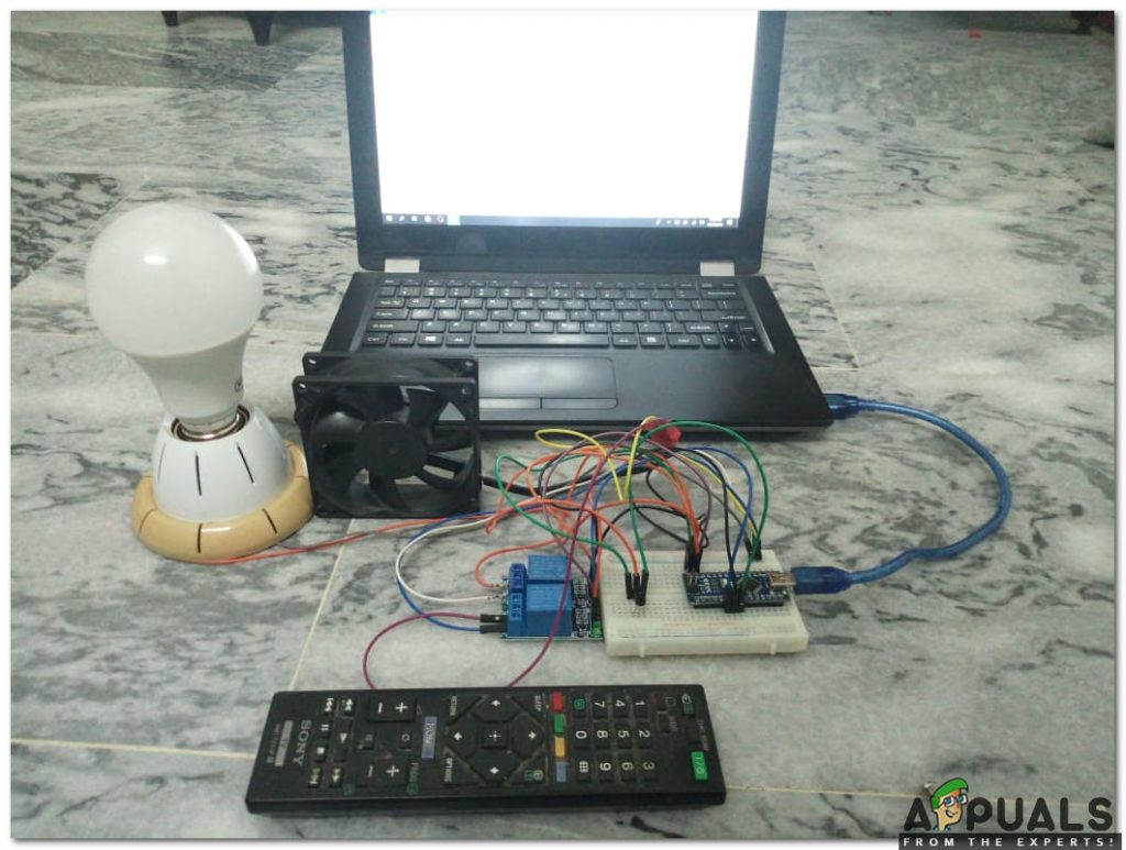
In this project, we will use a simple TV remote to make a simple home automation system. This TV remote will control all the appliances connected to the microcontroller board.
How to Use a TV Remote to Make Home Automation System?
Home Automation systems that are already available in the market, are very costly. We can use an Arduino board to connect different home appliances and control them using a TV remote. This will be very low in cost and an efficient way to automate the house. Now let us move a step ahead and start collecting information to start the project.
Step 1: Collecting the Components
The best approach to start any project is to make a list of components and going through a brief study of these components because no one will want to stick in the middle of a project just because of a missing component. A list of components that we are going to use in this project is given below:
- No products found.
- TSOP 1738 IR Receiver
- No products found.
- Remote Control
- Breadboard
- No products found.
Step 2: Studying the Components
Now as we know what components we are going to use, let us study them briefly to make a better understanding of how our circuit works.
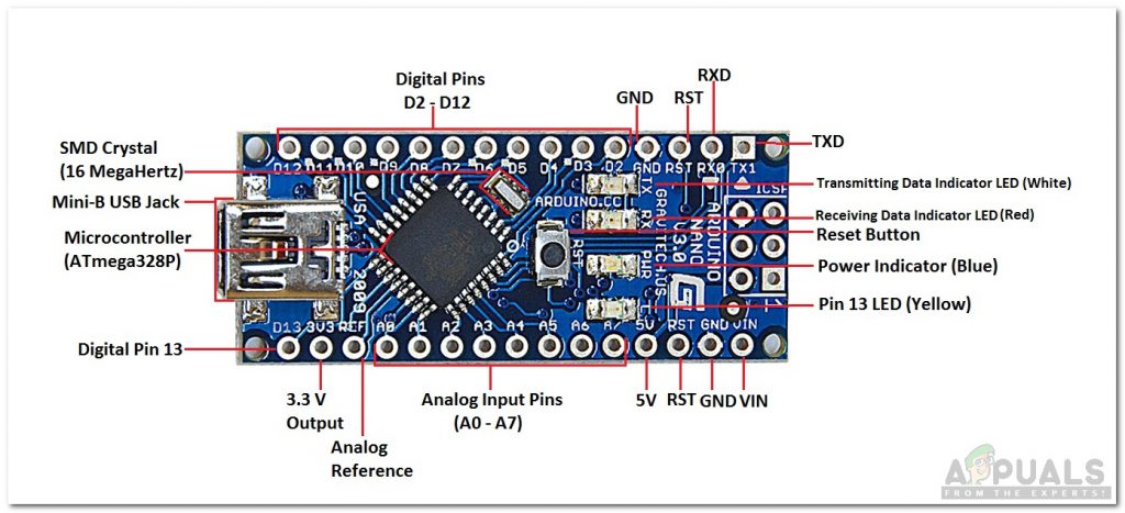
Arduino Nano is a microcontroller board that carries out various operations in different circuits. It requires a C Code that tells the board what tasks to perform and how. It has 13 digital I/O pins which mean that we can operate 13 different devices. If you want to control more than 13 devices, use Arduino Mega.
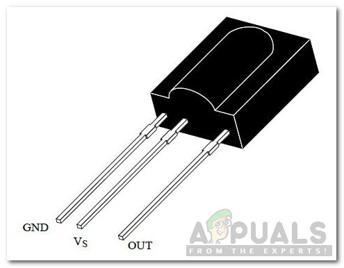
TSOP 1738 is an IR module for Remote Controles. It has a carrier frequency of 38kHz. It consists of a photodetector that detects the signal and then demodulates it. Its output is directly used by Arduino or any other microcontroller board.
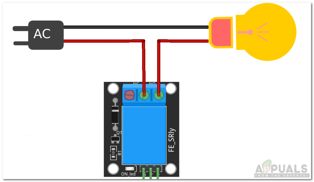
A relay module is a switching device. It works in two modes, Normally Open (NO) and Normally Closed (NC). In NO mode, the circuit is always broken unless you send a HIGH signal to the relay through Arduino. NC mode wors the other way around, The circuit is always complete unless you switch on the relay module. Make sure you connect the positive wire of your Electrical Appliance to the relay module in the way shown below.
A standard TV remote control has a power button and all the numerical keys on it. These numerical keys will be used for the switching of the electrical appliances.
Step 3: Making the Circuit
Now as we know how all the components work, let us move ahead and start making the circuit.
- Take a breadboard and insert your Arduino Nano and TSOP 1738 in it.
- Power up the TSOP 1738 module and the relay module through Arduino. Connect the OUT pin of TSOP1738 to pin11 of Arduino and also connect the IN pins of the relay module to Arduino. I am controlling only two electrical appliances so I’m using only relay modules here. If you want to control more appliances, similarly connect more relay modules.
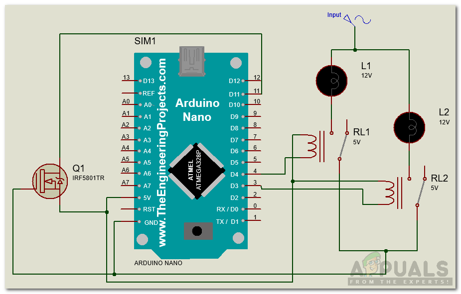
Circuit Diagram
Step 4: Getting Started with Arduino
If you haven’t worked on Arduino IDE before, don’t worry because a step by step to set up Arduino IDE is shown below.
- Connect your Arduino board to the PC and open Control Panel. Click on Hardware and Sound. Now open Devices and Printer and find the port to which your board is connected. In my case it is COM14 but it is different in different computers.
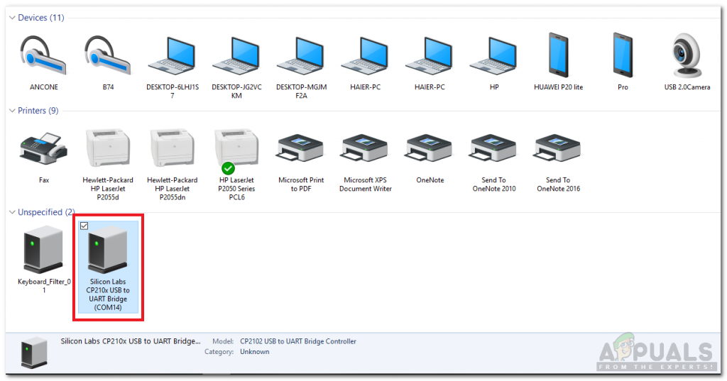
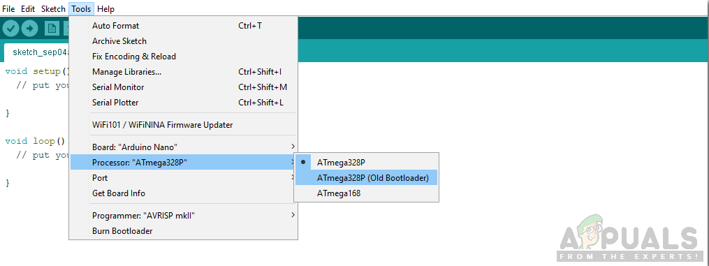
Finding Port - Click on the Tool menu and set the board as Arduino Nano (AT Mega 328P).
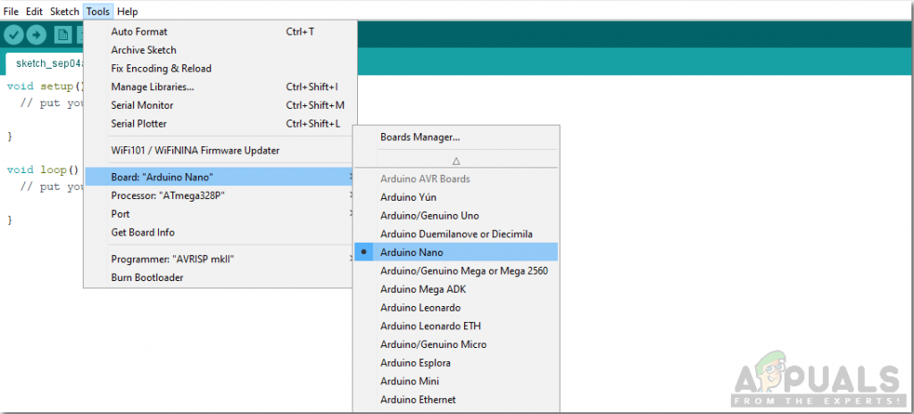
Setting Board - Click on the Tool menu again and set the port that you observed in the control panel before.
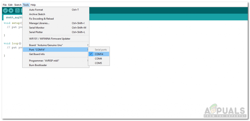
Setting Port - In the same Tool menu, set the Processor as ATmega328p (Old Bootloader).
Setting Processor - To decode the data sent by the Remote control, we need a special library for A code Arduino. This library is attached along with the code in the link below. To add the library goto Sketch > Include Library > Add ZIP Library. A box will appear. Find the ZIP folder on your computer and click OK to include the folder.
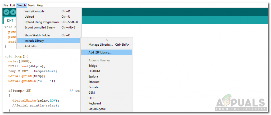
Include Library - Download the code attached below and click on the upload button to burn the code in your Arduino Nano board.
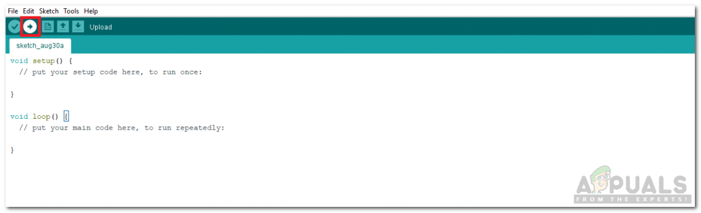
Upload
Click on the download button to get the code.
Step 5: Code
The code is very easy to understand but still, it is briefly described below.
1. void setup() is a function in which we initialize the INPUT or OUTPUT pins. This function also sets the baud rate by using Serial.begin() command. Baud Rate is the communication speed of the microcontroller.
2. void loop() is a function which runs repeatedly in a loop. In this loop, we write a code that tells the microcontroller board what tasks to carry out and how.
3. When we send data from the TV remote, Arduino needs to decode this data. For this, we have included a special library #include <IRremote.h>. A function in this library will be used to decode the data of each key, sent from the remote.
#include <IRremote.h>
int RECV_PIN = 11;
IRrecv irrecv(RECV_PIN);
decode_results results;

void setup() {
Serial.begin(9600);
irrecv.enableIRIn();
}

void loop() {
if (irrecv.decode(&results)) {
Serial.println(results.value, HEX);
irrecv.resume();
}
delay(100);
}
The above code is reading the values sent from the remote and decoding it to its corresponding HEX value. This code is taken from the examples of the IRremote library in Arduino IDE. This code is also attached in the download link by the name test.ino provided above. The output of this function, when all the numeric keys are pressed, will be:
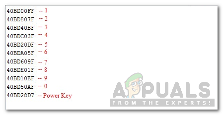
4. In the code.ino attached in the above download link, pins of Arduino that will be used are initialized. In the void loop() function, when a button on the remote is pressed, the initially False condition is turned to True and the respective relay is switched on. If the same button is pressed again, It will toggle the boolean condition and switch the relay off. The power button will turn all the Relays on or off.
void loop()
{
if (irrecv.decode(&results))
{
Serial.println(results.value,HEX);
delay(100);

if(results.value==0x40BD00FF)
{
i=!i;
digitalWrite(IN1, i);

}

if(results.value==0x40BD807F)
{
j=!j;
digitalWrite(IN2, j);

// delay(200);
}

if(results.value==0x40BD28D7)
{
m=!m;
digitalWrite(IN1, m);
digitalWrite(IN2, m);
digitalWrite(IN3, m);
digitalWrite(IN4, m);

// delay(200);
}
irrecv.resume(); // Receive the next value
//delay(100);
}
}
This was the whole procedure to make a simple Home Automation System controlled by a TV remote control. Now, you can connect relay modules according to the number of your appliances and enjoy your own Smart Home Automation System.


