How To Control Your Car Ignition System Through Serial Communication?
There are several SmartStart systems available in the market that automate your car’s ignition system like Viper SmartStart but they are very costly. Although they include Remote start, stop and location tracking, etc hence, they require many alterations in the genuine circuitry of the car. Making alterations in the circuity can be hazardous because it can lead to short circuits and these aftermarket systems are expensive too. Today I will design a system that follows the Bluetooth transmission concept to start the engine and it also allows the owner of the car to set a password to keep the car protected from thieves. If someone tries to steal the car, he would not be able to do so due to password protection. As soon as the wrong password is entered using the keypad the ignition switch will not be turned on. The On-Board Diagnostics board that is responsible for controlling all the functions of the car cannot be reset when we will install our circuit in the car. Now, without wasting a second let’s get to work.
How To Design Anti-Theft Ignition Circuit?
Now as we know the abstract of the project, let us move forward and gather different information to start working. We will first make a list of the components and then assemble all the components together to make a working system.
Step 1: Components Needed (Hardware)
Step 2: Components Needed (Software)
- Proteus 8 Professional (Can be downloaded from Here)
Step 3: Block Diagram
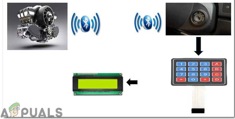
In this project I have designed two block diagrams to elaborate the purpose of the project clearly. First one shows the traditional ignition system that is most commonly used in all of the cars that are assembled nowadays. The second one shows our ignition system that I have designed in this project that can be installed in the cars to make them more secure.
- Traditional Ignition System:

Factory Designed System - Modified Ignition System:
Modified System
Step 4: Working Principle
In our ignition system, the wires will not be controlled by the On-Board Diagnostics Port but they will work autonomously. There are several electronic gadgets available in the market that have the ability to reset the OBD Port and the computers that are present in the engines. The electronic circuit will have two portions. One will be installed at the ignition switch side and the second one will be placed at the engine side. Wireless transmission of the Bluetooth signals will take place between these two sides. The primary circuit will comprise an ignition switch, Arduino, LCD, keypad and HC-06. The secondary side of the circuit will comprise of an Arduino, Relay module, HC-06, and buzzer. As soon as the key moved to start the car the LCD is turned ON and allows the driver to enter the password that is set by him/her initially in the Code. If the driver enters the correct password only then the signal is received at the engine side by the Bluetooth module and the key is moved further that will trigger the Relay circuit and the fan will be turned ON. Now, in order to start the car, we need to move the key towards the ignition position that will allow the car to be started. As soon as the car is started the system will display ON on the LCD and as soon as the key is moved in reverse position the car will be turned OFF but the wireless connection remains until the key isn’t fully moved backward. If the multiple wrong attempts are done to start the car then the alarm is generated using the buzzer that will alert the people passing by or the owner of the car if he/she is not far away from the car.
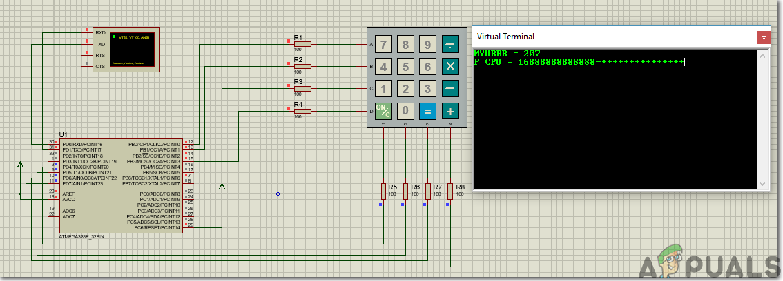
Step 5: Simulate The Circuit
Before making the circuit it is better to simulate and examine all the connections on a software. The software we are going to use is the Proteus Design Suite. Proteus is a software on which electronic circuits are simulated.
- After you download and install the Proteus software, open it. Open a new schematic by clicking the ISIS icon on the menu.
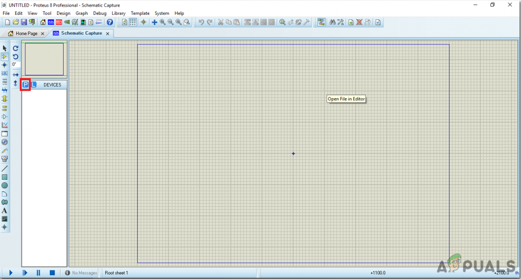
New Schematic - When the new schematic appears, click on the P icon on the side menu. This will open a box in which you can select all the components that will be used.
- Now type the name of the components that will be used to make the circuit. The component will appear in a list on the right side.
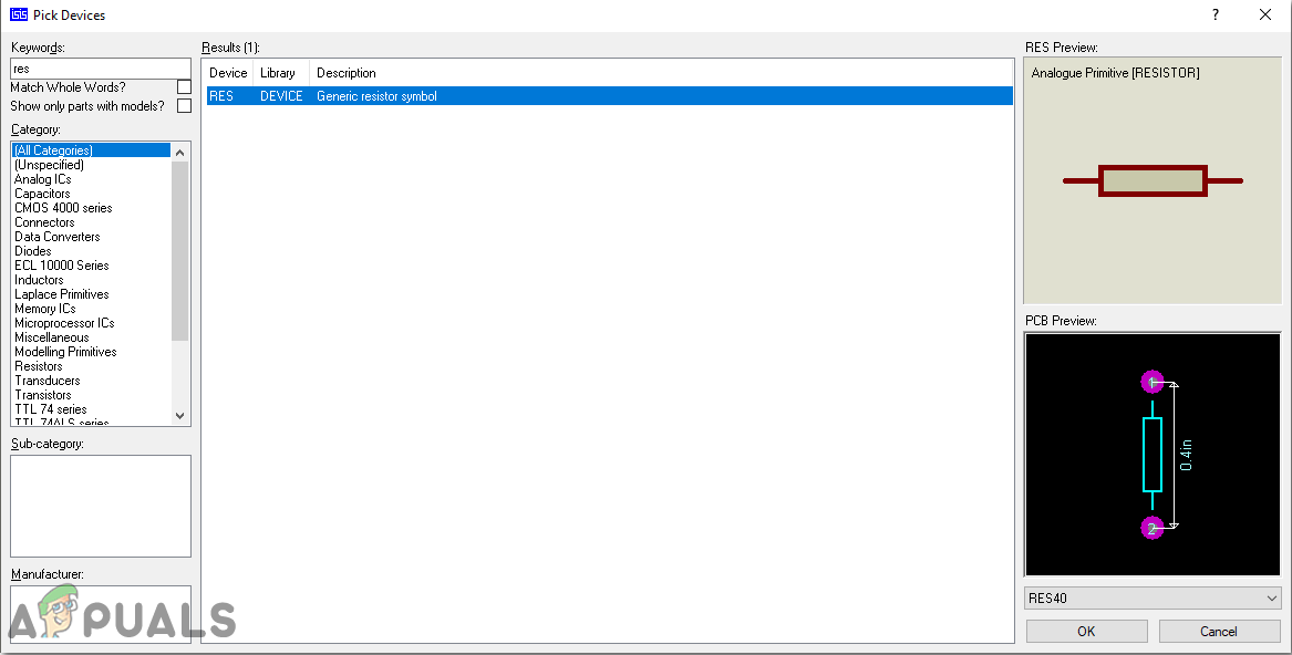
Selecting Components - In the same way, as above, search all the components as above. They will appear in the Devices List.
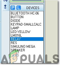
Search Components
Step 6: Circuit Diagrams
- Primary Side:
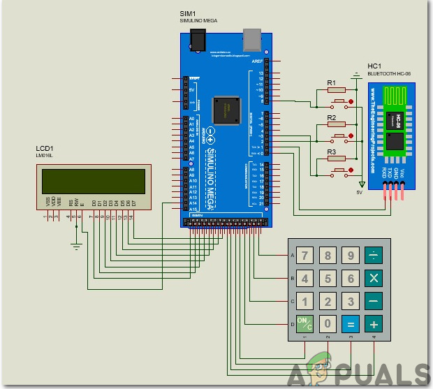
Primary Circuit - Secondary Side:
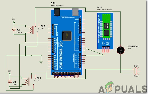
Secondary Circuit
Step 7: Getting Started With Arduino
If you haven’t worked on Arduino IDE before, don’t worry because a step by step to set up Arduino IDE is shown below.
- Download the latest version of Arduino IDE from Arduino.
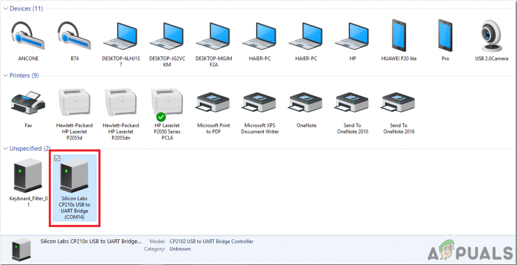
- Connect your Arduino board to the PC and open Control Panel. Click on Hardware and Sound. Now open Devices and Printer and find the port to which your board is connected. In my case it is COM14 but it is different in different computers.
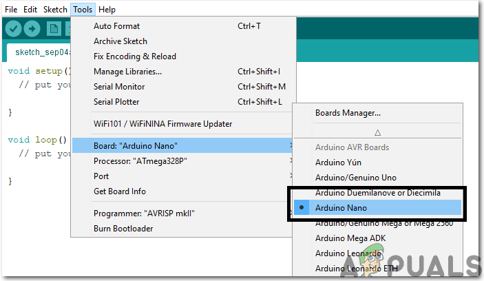
Finding Port - Click on the Tool menu and set the board as Arduino Nano (AT Mega 328P).
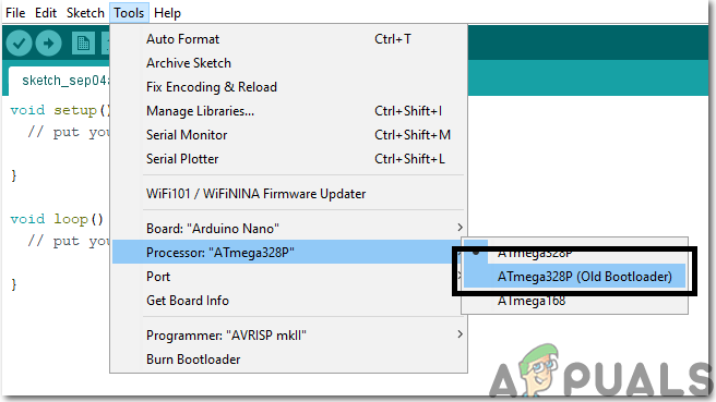
Setting The Board - In the same Tool menu, set the Processor as ATmega328p (Old Bootloader).
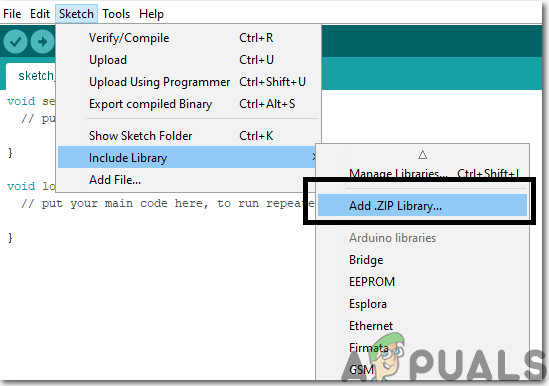
Setting The Processor - We will have to include a library to use the LCD Module. The library is attached below in the download link along with the code. Go to Sketch > Include Library > Add .ZIP Library.
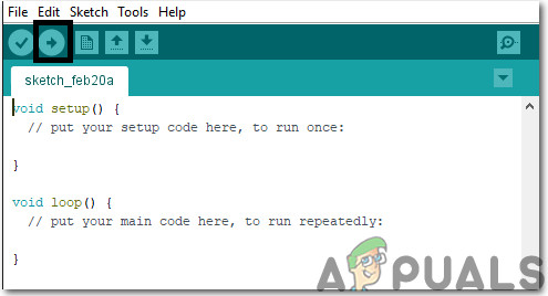
Include Library - Download the code attached below and paste it into your Arduino IDE. Click on the upload button to burn the code on your microcontroller.
Upload The Code
Download the code and necessary libraries by clicking Here.
Step 8: Code
The code for this project is pretty simple and well commented.
- void setup() is a function in which we initialize the INPUT or OUTPUT pins. This function also sets the baud rate by using Serial.begin() command. Baud Rate is the communication speed of the Arduino.
- void loop() is a function which runs repeatedly in a loop. In this loop, we write a code that tells the microcontroller board what tasks to carry out and how.
#include <Password.h>
#include <LiquidCrystal.h>  //Necessary Library For LCD Module
#include <Keypad.h>         //Necessary Library For 4x4 Keypad

int ignition = 5;          //Pin 5 Used For Triggering Relay
int alarm = 6;             //Pin 6 Used For Triggering Buzzer

int pos = 0;
LiquidCrystal lcd(2,3,4,9,10,11,12);
Password password = Password( "4321" );  //Apprise This Password To The Driver
const byte ROWS = 4; // Four rows
const byte COLS = 3; // Three columns
// Define the Keymap
char keys[ROWS][COLS] = {
{'1','2','3',},
{'4','5','6',},
{'7','8','9',},
{'*','0',' ',}
};

// Connect keypad ROW0, ROW1, ROW2 and ROW3 to these Arduino pins.
byte rowPins[ROWS] = {25, 24, 23, 22}; //connect to the row pinouts of the keypad
byte colPins[COLS] = {28, 27, 26}; //connect to the column pinouts of the keypad
const int buttonPin = 7;
int buttonState = 0;

// Create the Keypad
Keypad keypad = Keypad( makeKeymap(keys), rowPins, colPins, ROWS, COLS );

void setup() {
pinMode(buttonPin, INPUT);
lcd.begin(16, 2);
digitalWrite(ledPin, LOW); // sets the LED on
Serial.begin(9600);
keypad.addEventListener(keypadEvent); //add an event listener for this keypad
keypad.setDebounceTime(250);
}

void loop() {
keypad.getKey();
buttonState = digitalRead(buttonPin);
if (buttonState == HIGH)
{
lcd.clear();
}
keypadEvent();

}

void keypadEvent(KeypadEvent eKey){
switch (keypad.getState()){
case PRESSED:
lcd.print(eKey);
switch (eKey){
case ' ': guessPassword();
digitalWrite(ignition,HIGH);
digitalWrite(alarm,HIGH);
break;
default:
password.append(eKey);
}
}}

void guessPassword(){
if (password.evaluate()){
digitalWrite(ledPin,HIGH);
delay(500);
lcd.print("VALID PASSWORD "); //
password.reset(); //resets password after correct entry
delay(600);
lcd.print("ON");
delay(2000);
lcd.clear();
}
else{
digitalWrite(ledPin,LOW);
lcd.print("INVALID PASSWORD ");
password.reset(); //resets password after INCORRECT entry
delay(600);
lcd.clear();
}
}
Step 7: Hardware Design
As we have now simulated the circuit on software and understood the code, now let us move ahead and place the components on the Breadboard. Firstly, we will assemble the primary side circuit and then we will assemble the secondary side circuit.
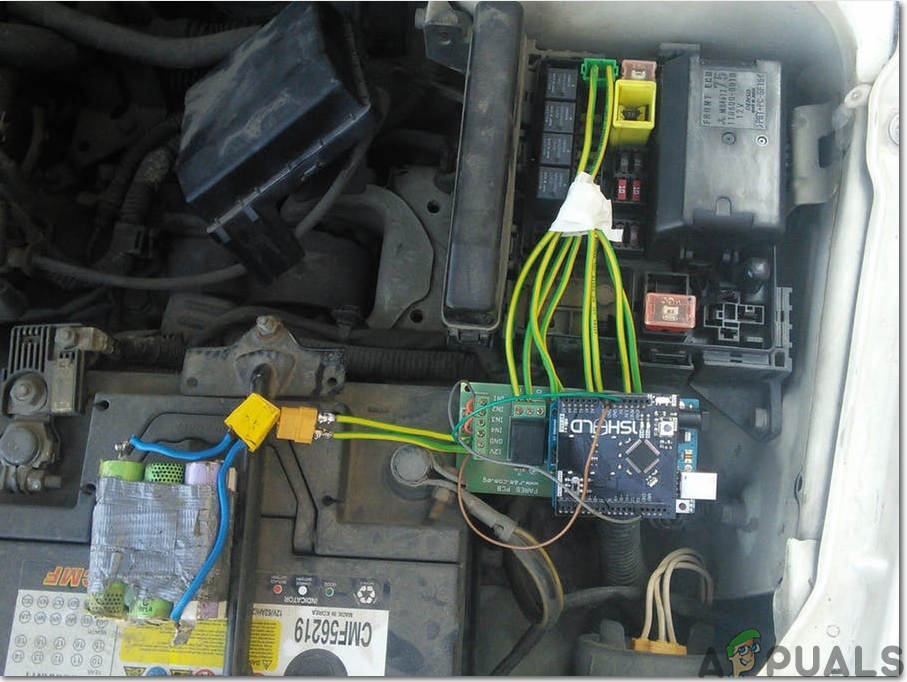
It is better to connect the circuit with the audio system of the car so that it will be difficult for the burglars to find that circuit and they will take more time to reach behind the dashboard of the car because it will be placed behind it. The audio system of the car will be connected to the switch and further to the DC battery to turn ON the audio system. When the user enters the correct password by using the 4×4 keypad the wireless connection is established between both sides and he/she will have to rotate the key again to start the car. Assemble all of the connections on the breadboard and use double tape to paste the circuit behind the audio system of the car.
Now, we will assemble the secondary side of the circuit that is also known as the engine side. At this side, we will connect the Relay module with the Arduino and it will be triggered only when it receives a signal from the Bluetooth module. If the driver enters the wrong password in multiple attempts then the alarm will start ringing and people passing nearby will become to know that there is some issue in the car. Place the components on the breadboard according to the circuit diagram shown above and attach the circuit to the radiator water bottle.
Recommendations
- Apply heat sinks on the components that are placed on the engine side so that when the car heats up short circuit could be avoided.
- The GPS and GSM modules can be added in the circuit to determine the location of the car and ensure security by turning OFF engine through SMS.
- Face recognition can also be implemented in this system so that as soon as the face of the owner is recognized the car is turned ON.


