How To Make An Audio Amplifier Circuit?
A very important part of Sound Electronics is a Power Amplifier. Its main task is to increase the amplitude of the power of the given input signal. It amplifies the power of the input signal so that it becomes able to drive the loads like loudspeakers or headphones etc. Normal amplifiers that are used to amplify the AC signal’s voltage are not able to provide the current. this makes them unable to drive the load. But power amplifier provides this necessary current that is required to drive the output load.
In this article, we are going to design a 10 Watt amplifier, to which an 8-ohm speaker will be connected as load. The required power will be delivered to the load by using an operational amplifier IC LF351 and two power transistors, TIP127 and TIP122.
How to design a Power Amplifier Circuit Using Power Transistors?
Now, as we know the abstract of our project, let us move forward and test the circuit after making the component list.
Step 1: Gathering The Components
Before starting a project, one must know what components he is going to need while working either it is a hardware component or computer software. An excellent approach that one can adopt to start a project is to make a complete list of all the components that he is going to use in a particular project. We can save a lot of time while working on a project if we have this list of components. So, a complete list of components that we are going to use in this project is given below:
- Aluminium heat sink
- 8 Ohms 10 Watt speaker
- 4.7k-ohm Resistor (x3)
- 200-ohm Resistor (x2)
- 3.3k-ohm Resistor
- 10pF Capacitor
- 82uF Capacitor
- 2 pin connectors (x2)
- No products found.
- No products found.
- No products found.
- 12V variable power supply
- No products found.
- Connecting wires
- No products found.
Step 2: Circuit Design
Usually, a Power Amplifier is the last block in an amplifier chain system. It is directly connected to load. Usually, voltage-controller amplifiers and preamplifiers amplify the input signal before sending it to the power amplifier.
In Audio Amplifier Systems, most of the time, the load used is a Loud Speaker. Load impedance plays an important role in the output of the power amplifier. So, a proper load must be selected while connecting on the output terminal of the circuit.
The LM351 is an integrated circuit that will amplify the input signal. Two power transistors are used that will provide the necessary power amplification. The transistors directly take the power from the power supply and give them to the load. As the input signal is AC, it will change its polarity. So both transistors will help to provide the power amplification to the opposite pole i.e., TIP127 will provide the power amplification to the positive peak and the negative peak will be provided power amplification by the TIP122.
Step 3: Simulating The Circuit
As we know have a complete list of all the components that we are going to use in this project, let us move a step ahead and test the circuit. Before making this circuit on hardware, let us do the simulation of this circuit on a computer software first. Simulating a circuit on software before implementing it on hardware is an excellent approach because it makes us assure that the circuit works perfectly fine and if there are some drawbacks, they can be corrected immediately on the computer. The software that we are going t use for the simulation purposes is Proteus. This software allows us to design a circuit on the computer and test its output by giving it an appropriate input. To simulate the circuit, go through the following steps:
- If you don’t have this software installed on your computer already, click here to download it.
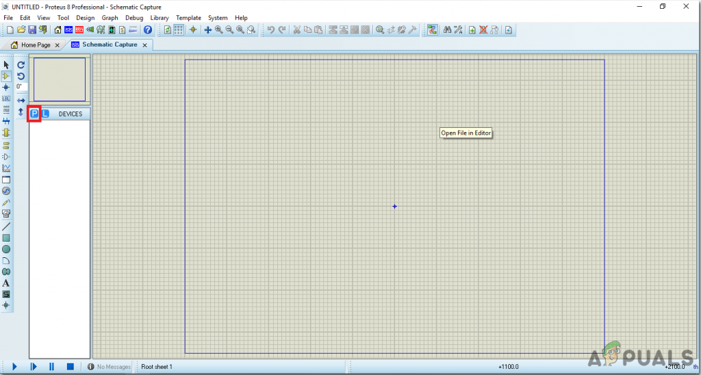
- After the software is installed, open the software and make a new project by click on the ISIS button.

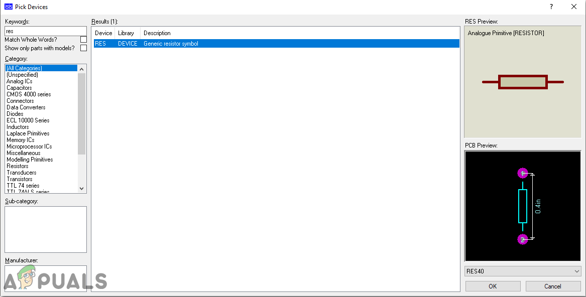
ISIS - A new schematic has just opened. Click on the P button to open the component menu.
New Schematic - A box will appear containing a search bar on the top left corner. Search the component that you need to use in the project.
Selecting Components - After selecting all the components, you will see a complete list on the left side of the screen.
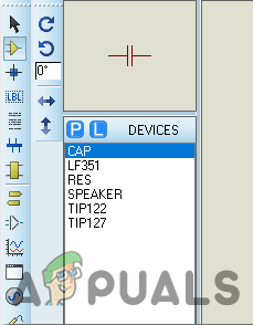
Component List - Make a circuit diagram, as shown below.
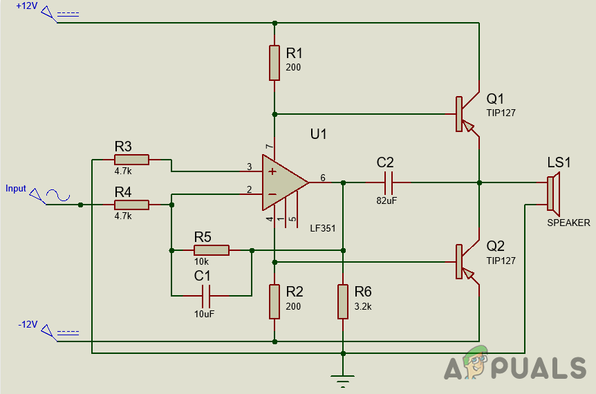
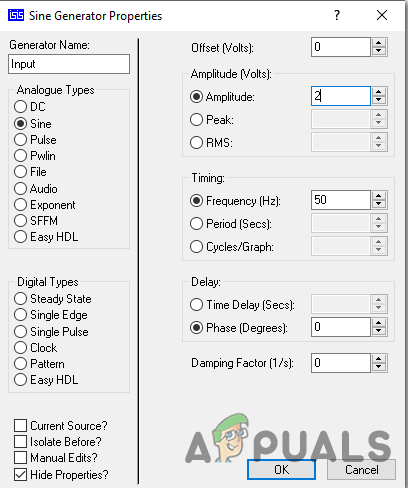
Circuit Diagram - Now click on the Input terminal and set the amplitude of the AC signal to 1V and the frequency to 50Hz.
Set AC signal - Now replace the speaker with an 8-ohm resistor. Place an Oscilloscope on the schematic and connect its A terminal to the input and the B terminal to the output.
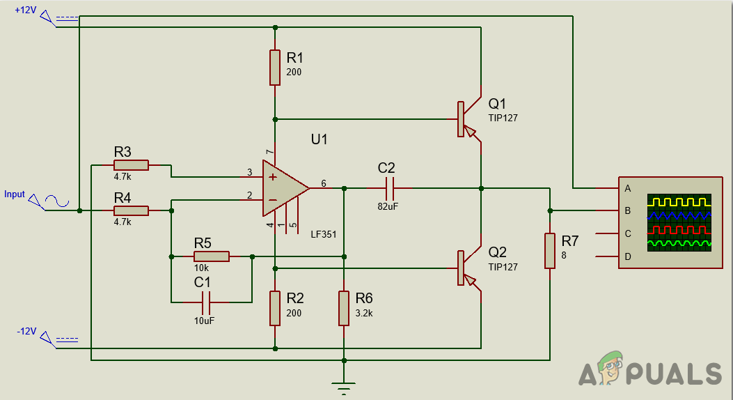
Connecting Oscilloscope - Now run the simulation. Examine the output waves. You will notice the output wave will have a bigger amplitude.
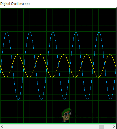
Output
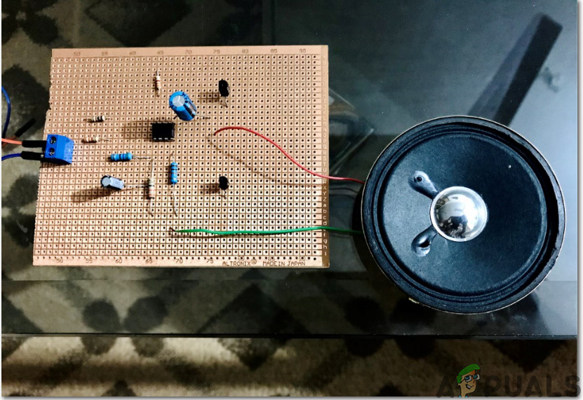
Step 4: Making The circuit
Now as we have simulated the circuit, let us make the hardware of this project on Veroboard. To implement this circuit on hardware, go through the following steps. One thing must be kept in mind that all the components must be placed close to each other and the circuit should be compact.
- Take a Veroboard and rub its side with the copper coating with a scraper paper.
- Now Place the components carefully and close enough so that the size of the circuit does not become very big
- Carefully make the connections using solder iron. If any mistake is made while making the connections, try to desolder the connection and solder the connection again properly, but in the end, the connection must be tight.
- Once all the connections are made, carry out a continuity test. In electronics, the continuity test is the checking of an electric circuit to check whether current flow in the desired path (that it is in certainty a total circuit). A continuity test is performed by setting a little voltage (wired in arrangement with a LED or commotion creating part, for example, a piezoelectric speaker) over the picked way.
- If the continuity test passes, it means that the circuit is adequately made as desired. It is now ready to be tested.
- Connect the positive and negative terminal of the power supply in the circuit. and set the knob of the power supply to 12V.
- Apply AC input to the input terminal and examine the sound produced by the speaker.
So this was the whole procedure to make a power amplifier circuit. Now you can enjoy making this circuit at home.


