How To Measure Distance Between Two Points Using Arduino?
In Electronics, most of the time Ultrasonic Sensors are used to measure the distance from one particular point to another. It is very easy to write a code on the Arduino board and integrate an ultrasonic sensor to carry out this task. But in this article, we are going to adopt a different approach. We are going to use two separate ultrasonic sensors that will be integrated with two separate Arduino. These two modules will be placed at two different points between which the distance is to be measured. One sensor will be made a receiver and the other will be made a transmitter. By doing so, we will be able to measure the distance between them just by locating the position of the transmitter by using many ultrasonic receivers. The Technique we are using here is called Triangulation.
The Technique used here is just useful on small scale systems where a small distance is to be found. To implement it on a large scale, some modifications are surely needed. All the challenges that were faced while carrying out this project are discussed below.
How to Use Arduino and Ultrasonic Sensor To Measure Distance?
As we know the summary behind the project, let us move ahead and gather further information to start the project.
Step 1: Gathering The Components (Hardware)
If you want to avoid any inconvenience in the middle of any project, the best approach is to make a complete list of all the components that we are going to use. The second step, before starting to make the circuit, is to go through a brief study of all these components. A list of all the components that we need in this project is given below.
- No products found.
- No products found.
- No products found.
- No products found.
- No products found.
Step 2: Gathering The Components (Software)
- Proteus 8 Professional (Can be downloaded from Here)
After downloading the Proteus 8 Professional, design the circuit on it. I have included software simulations here so that it may be convenient for beginners to design the circuit and make appropriate connections on the hardware.
Step 3: Working of The HCR-05
As we now know the main abstract of our project, let us move ahead and go through a brief study of the working of HCR-05. You can understand the main working of this sensor by the following diagram.
This sensor has two pins, trigger pin, and eco pin that are both used to measure the distance between two particular points. The process is initiated by sending an ultrasonic wave from the sensor. This task is done by triggering the trig pin for 10us. An 8 sonic burst of ultrasonic waves is sent from the transmitter as soon as this task is done. this wave will travel in the air and as soon as it strikes an object in its way, it will strike back and received by the receiver built in the sensor.
When the ultrasonic wave will be received by the receiver after reflecting the sensor, it will put the eco pin to a high state. This pin will remain in the high state for the duration of time that will be exactly equal to the time taken by the ultrasonic wave to travel from the transmitter and back to the receiver of the sensor.
To make your ultrasonic sensor transmitter only, just make the trig pin as your output pin and send a high pulse to this pin for 10us. An ultrasonic burst will be initiated as soon as this is done. So, whenever the wave is to be transmitted, just the trigger pin of the ultrasonic sensor is to be controlled.
There is no way to make the ultrasonic sensor as a receiver only because the rise of the ECO pin can not be controlled by the microcontroller because it is related to the trig pin of the sensor. But there is one thing that we can do is, we can cover the transmitter of this ultrasonic sensor with duct tape s that no UV wave gets out. Then the ECO pin of this transmitter will not be affected by the transmitter.
Step 4: Working of The Circuit
Now, as we have made both the sensors to work separately as a transmitter and a receiver, there is a big problem that is faced here. The receiver will not know the time taken by the ultrasonic wave to travel from the transmitter to the receiver because it does not know exactly when this wave was transmitted.
To solve this problem, what we have to do is to have to send a HIGH signal to the ECO of the receiver as soon as the ultrasonic wave is transmitted bu the transmitter sensor. Or in simple words, we can say that the ECO of the receiver and the trigger of the transmitter should be sent to HIGH at the same time. So, to achieve this, we will somehow make the trigger of the receiver go high as soon as the trigger of the transmitter goes high. This trigger of the receiver will stay high until the ECO pin goes LOW. When an ultrasonic signal will be received by the ECO pin of the receiver, it will go LOW. This will mean that the trigger of the transmitter sensor just got a HIGH signal. Now, as soon as the ECO goes low, we will wait for the known delay and put the receiver’s trigger HIGH. By doing so, the triggers of both the sensors will be synced and the distance will be calculated by knowing the time delay of the wave travel.
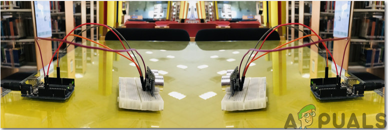
Step 5: Assembling The Components
Even though we are using only the transmitter of one ultrasonic sensor and the receiver of the other, but it is mandatory to connect all of the four pins of the ultrasonic sensor to the Arduino. To connect the circuit, follow the steps given below:
- Take two ultrasonic sensors. Cover the receiver of the first sensor and the transmitter of the second sensor. Use white duct tape for this purpose and make sure that these two are fully covered so that no signal leaves the transmitter of the second sensor and no signal gets into the receiver of the first sensor.
- Connect two Arduino on two separate breadboards and connect their respective sensors with them. Connect the trigger Pin to pin9 of Arduino and ecoPin to the pin10 of the Arduino. Power up the ultrasonic sensor by the 5V of Arduino and common all the grounds.
- Upload the receiver code to the Arduino of the Receiver and the transmitter code to the Arduino of the transmitter.
- Now open the serial monitor of the receiving side and note the distance that is being measured.
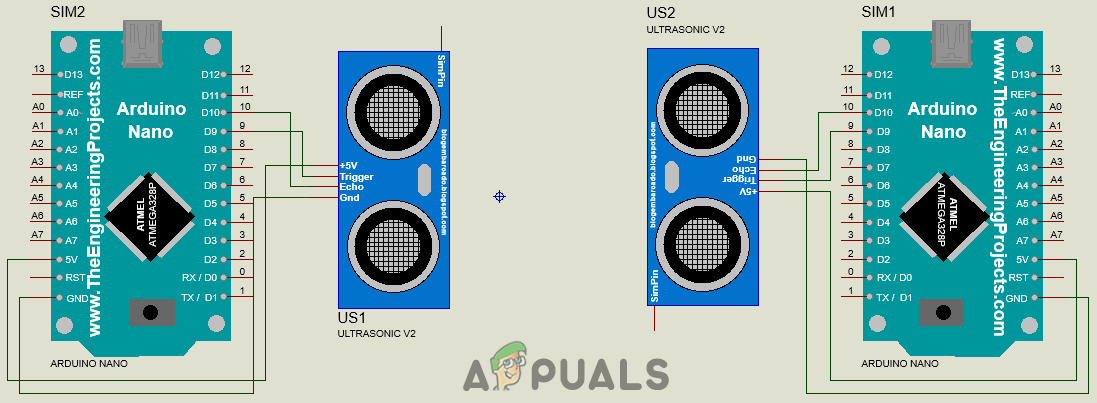
The circuit diagram of this project looks like:
Step 6: Getting Started With Arduino
If you are not already familiar with the Arduino IDE, don’t worry because a step by step procedure to set-up and use Arduino IDE with a microcontroller board is explained below.
- Download the latest version of Arduino IDE from Arduino.
- Connect your Arduino Nano board to your laptop and open the control panel. in the control panel, click on Hardware and Sound. Now click on Devices and Printers. Here, find the port to which your microcontroller board is connected. In my case it is COM14 but it is different on different computers.

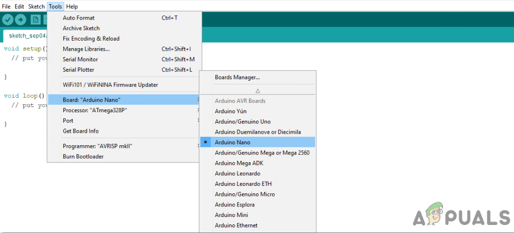
Finding Port - Click on the Tool menu. and set the board to Arduino Nano from the drop-down menu.
Setting Board - In the same Tool menu, set the port to the port number that you observed before in the Devices and Printers.

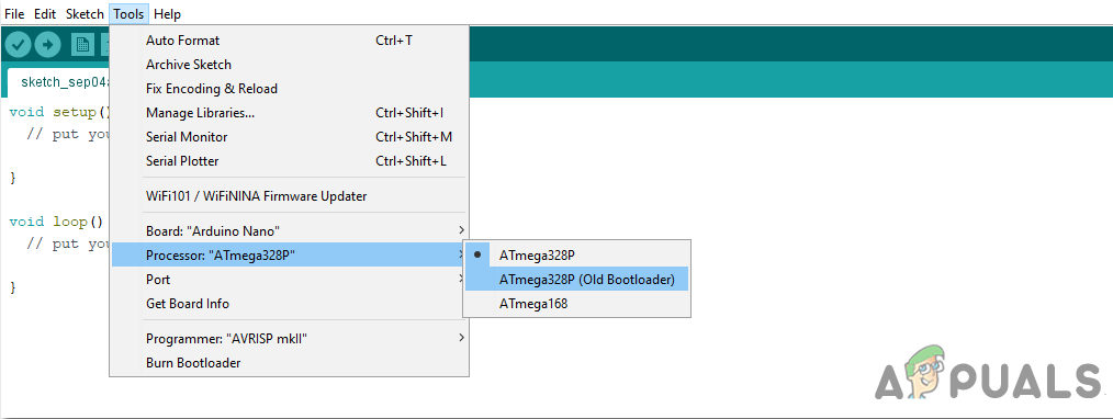
Setting Port - In the same Tool menu, Set the Processor to ATmega328P (Old Bootloader).
Processor - Download the code attached below and paste it into your Arduino IDE. Click on the upload button to burn the code on your microcontroller board.
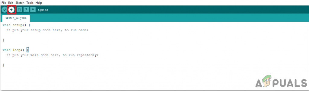
Upload
To download the code, click here.
Step 7: Understanding The Code
The code used in this project is very simple and quite well commented. There are two files of codes in the attached folder. Code for the transmitter and a code for the receiver side both are given separately. We will upload these codes in both of the respective Arduino boards. Although it is self-explanatory, it is briefly described below.
Code For Transmitter Side
1. At the start, pins of the Arduino board are initialized that will be connected to the Ultrasonic Sensor. Then the variables are declared which will be used to store values for the calculation of time and distance during the run time of the code.
// defines pins numbers
const int trigPin = 9;  // Connect the trig pin of ultrasonic sensor to pin9 of Arduino
const int echoPin = 10; // Connect the eco pin of ultrasonic sensor to pin10 of Arduino
// defines variables
long duration;          // variable to storore the time taken by the ultrasonic wave t travel
int distance;           // variable to store distance calculated
2. void setup() is a function that runs only one time in the start when the board s powered on or the enable button is pressed. Here both the pins of Arduino are declared to be used as INPUT and OUTPUT. Baudrate is set in this function. Baud rate is the speed in bits per second by which the microcontroller communicates with the ultrasonic sensor.
void setup() {
 pinMode(trigPin, OUTPUT); // Sets the trigPin as an Output
 pinMode(echoPin, INPUT);  // Sets the echoPin as an Input
 Serial.begin(9600);       // Starts the serial communication
}
3. void loop() is a function that runs again and again in a loop. Here we have coded the microcontroller so that it sends a HIGH signal to the Trigger pin of the ultrasonic sensor, wits for 20 microseconds and send a LOW signal to it.
void loop() {
// Sets the trigPin on HIGH state for 10 micro seconds
digitalWrite(trigPin, HIGH); // send a HIGH signal on the trigger of first sensor
delayMicroseconds(10);       // wait for 10 micro seconds
digitalWrite(trigPin, LOW);  // send a LOW signal to the trigger of the first sensor
delay(2);                    // wait for 0.2 seconds
}
Code For Receiver Side
1. At the start, pins of the Arduino board are initialized that will be connected to the Ultrasonic Sensor. Then the variables are declared which will be used to store values for the calculation of time and distance during the run time of the code.
// defines pins numbers
const int trigPin = 9;  // Connect the trig pin of ultrasonic sensor to pin9 of Arduino
const int echoPin = 10; // Connect the eco pin of ultrasonic sensor to pin10 of Arduino
// defines variables
long duration;          // variable to storore the time taken by the ultrasonic wave t travel
int distance;           // variable to store distance calculated
2. void setup() is a function that runs only one time in the start when the board s powered on or the enable button is pressed. Here both the pins of Arduino are declared to be used as INPUT and OUTPUT. Baudrate is set in this function. Baud rate is the speed in bits per second by which the microcontroller communicates with the ultrasonic sensor.
void setup() {
 pinMode(trigPin, OUTPUT); // Sets the trigPin as an Output
 pinMode(echoPin, INPUT);  // Sets the echoPin as an Input
 Serial.begin(9600);       // Starts the serial communication
}
3. void Trigger_US() is a function that is will be called for Fake Triggering of the trig pin of the second ultrasonic sensor. We will sync the trigger time of the trig pin of both the sensors.
void Trigger_US()
{
 // Fake trigger the US sensor
 digitalWrite(trigPin, HIGH); // Send a HIGH signal to the trigger pin of Second sensor
 delayMicroseconds(10);       // wait for 10 micro secnds
 digitalWrite(trigPin, LOW);  // send a LOW signal to the trigger pin second sendor
}
4. void Calc() is a function that is used to calculate the time taken by the ultrasonic signal to travel from the first sensor to the second sensor.
void Calc() // function to calulate the time taken by the ultrasonic wave to travel
{
 duration=0;                         // duration initially set to zero
 Trigger_US();                       // call the Trigger_US function
 while (digitalRead(echoPin)==HIGH); // while the status of eo pin in high
 delay(2);                           // put a delay of 0.2 seconds
 Trigger_US();                       // call the Trigger_US function
 duration = pulseIn(echoPin, HIGH);  // calulate the time taken
}
5. Here in the void loop() function, we are calculating the distance by using the time taken by the ultrasonic signal to travel from the first sensor to the second sensor.
void loop() {
Pdistance=distance;
Calc();                                // call the Calc() function
distance= duration*0.034;              // calulating the distance covered by the ultrasonic wave
if (Pdistance==distance || Pdistance==distance+1 || Pdistance==distance-1 )
{
Serial.print("Measured Distance: ");  // print on serial monitor
Serial.println(distance/2);           // print on serial monitor
}
//Serial.print("Distance: ");
//Serial.println(distance/2);
delay(500);                           // wait for 0.5 seconds
} 


Hello,
do the transmitter and the receiver have to be in front of each other?
assume attaching a transmitter to a wall in the height of 1 meter and
a receiver to a robot moving to the wall in the height of 0.5 meters.
is it possible to measure the distance between them in this situation?