How to Translate Sign Language to Text Using Arduino?
We have consistently accepted that technology ought to be accessible for everybody and for good whether they are normal people or specially-abled individuals. The fundamental advantage of innovation is to engage individuals and improving them, not to conquer them but rather to help them.
People with the inability to speak use different means of communication to convey their messages. The most common of them is Sign Language. Sign language is a language that uses gesture modality to convey a message. Sign Language is common among the people who are not able to speak or listen. So, here is a project which will help you to translate the sign language into some text which will be understandable by other people.
How to use Arduino to make a Sign to text translator?
Now let us move towards gathering further data, analyzing it, making a circuit and burning the code on the microcontroller.
Step 1: Prerequisites
Before we start working, it is better to collect and study about the apparatus that we are going to use. A list below shows all the items that we need in this project.
- No products found.
- No products found.
- No products found.
- Resistors (470 ohms)
- Breadboard/Veroboard
- No products found.
- Female Headers
- Glove
Step 2: Setting up the Apparatus
We will use Flex sensors to detect the gesture. The flex sensor is a sensor that gives a different resistance and a different angle every time it is bent. It has two pins which are connected in a voltage divider configuration. The connection of these pins to the Arduino is shown below.
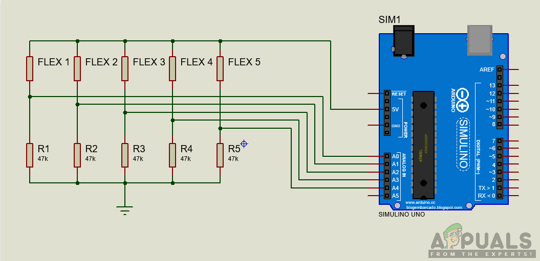
FLEX 1, FLEX 2, FLEX 3, FLEX 4, FLEX 5 are the flex sensors, and RES1, RES2, RES3, RES4, RES5 are the 470-ohm resistors. One point of all the flex sensors are common and 5V is applied to it. On the other end, one leg of all the resistors are common and connected to the ground. The input to the Arduino pins will receive analog data from 0 to 1023 which will be converted to the digital form in the code.
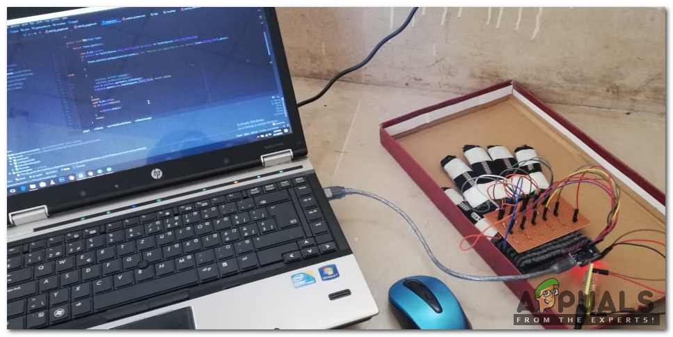
Now, as we know that how a flex sensor works, attach every flex sensor on the fingers of the glove (avoid using adhesives). Solder jumper wires to all the flex sensors and connects them on the Veroboard as shown in the above image. Solder the connections carefully and perform a continuity test. If the continuity test fails, recheck your soldered connections and fix them.
Step 3: Getting Started with Arduino
If you don’t have the Arduino IDE, download the latest version from Arduino
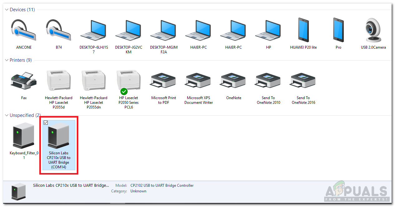
- Connect the Arduino with your PC and go to Control Panel > Hardware and Sound > Devices and Printers to check the name of the port to which Arduino is connected. On my PC it is COM14. It may be different on your PC.
Finding Port Number - Open your Arduino IDE and set the board to “Arduino /Genuino Uno”.
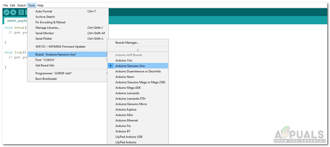
Setting Board - Open your Arduino IDE and set the port that you observer in your PC before.
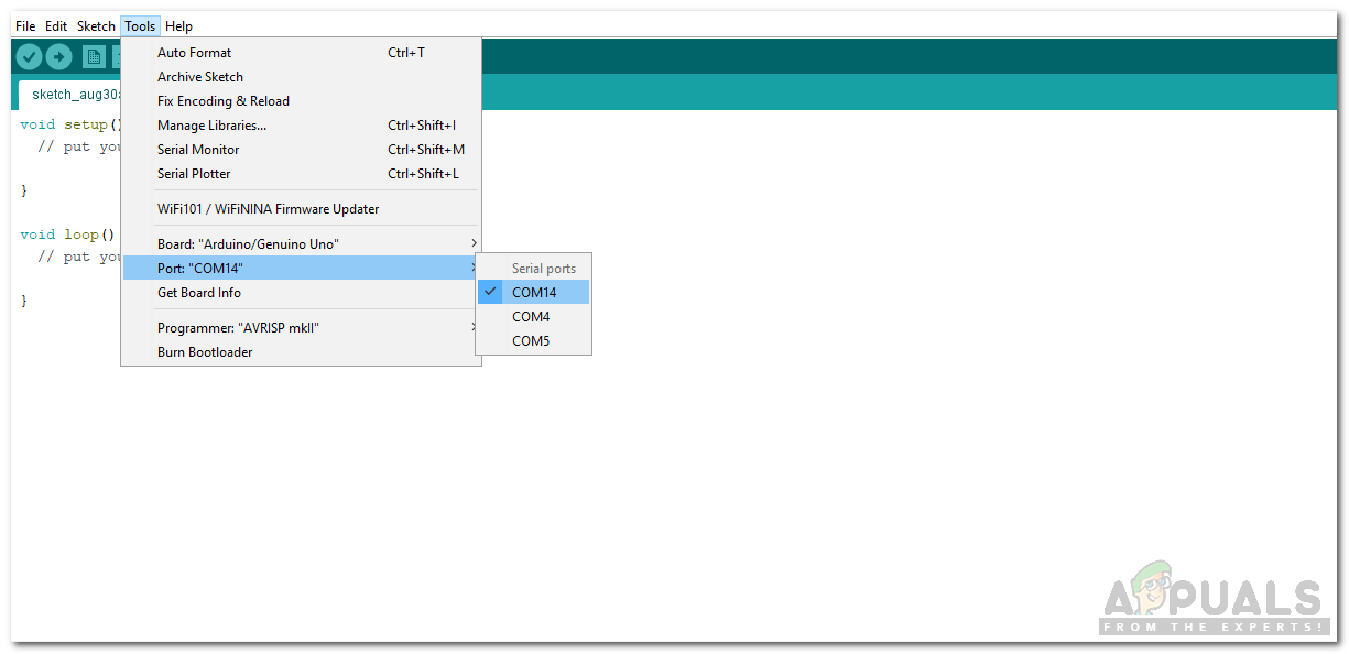
Setting Port - Now download the code attached below and upload it to your Arduino Board by clicking the Upload button.
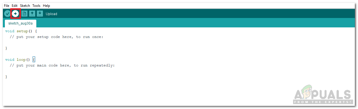
Upload
Download link: Click Here
Step 4: Code
The code is Commented well but here is some general explanation that how it works.
- In the start f the code, 5 analog pins of Arduino are initialized to be used with the flex sensors. Than the Vcc from the Arduino and 4.7k ohm resistance is initialized that is used in the circuit. Then the resistance of the straight flex sensor and the resistance at a 90-degree angle is initialized. These initializations will be helpful in writing the code.
- void setup() is a function in which we initialize the baud rate of the Arduino and all the five analog pins are initialized to be used as INPUT. Baud rate is the speed at which the microcontroller communicates.
- void loop() is a function that runs continuously again and again in a cycle. In this function, all the analog values are read and converted into digital values. Then, resistance is calculated by using the voltage divider formula and through that resistance, the bend angle of the flex sensor is calculated.
Once you have understood and uploaded the code, wear the gloves and do different gestures to translate them into text. In the code, you can add more combinations of finger movement of your choice and display the message accordingly. You will see that your sign language is now converted into text.
Step 5: Advanced
This project is all about converting the sign language to text and displaying it on the serial monitor. As the microcontroller used is Arduino, this device will work only when the Arduino is connected to the PC through a data cable because Arduino does not have a built-in WiFi Module. To make this project a little more interesting you can add an external WiFi module or use an ESP module instead of Arduino and get rid of the data cable and enjoy a sign to speech translation via WiFi.


