How To Ring Door Bell Automatically With Object Detection?
We all have doorbells outside our homes. Whenever a guest or a family member comes he looks for the bell and after finding out he/she rings it. Mostly it is observed that the guests can’t find the doorbell and if the height of a person is small it is very difficult for him to reach the doorbell. This problem is solved electronically. If we install a doorbell that uses an object detection circuit that rings automatically then there will be no more hassles.
So, here is the easiest way to make automatic doorbell with the help of components that are readily available in the market and home.
How To Design Automatic Doorbell Using Simple Infrared Sensor?
Firstly, we will gather the components and then assemble the circuit initially on software so that any beginner to electronics can assemble it easily and then on hardware for final testing.
Step 1: Components Used (Hardware).
- No products found.
- No products found.
- No products found.
- No products found.
- No products found.
- No products found.
- No products found.
- UM 66/555 timer IC
- Soldering Iron
Step 2: Components Used (Software).
- Proteus 8 Professional
This software can be downloaded from Here
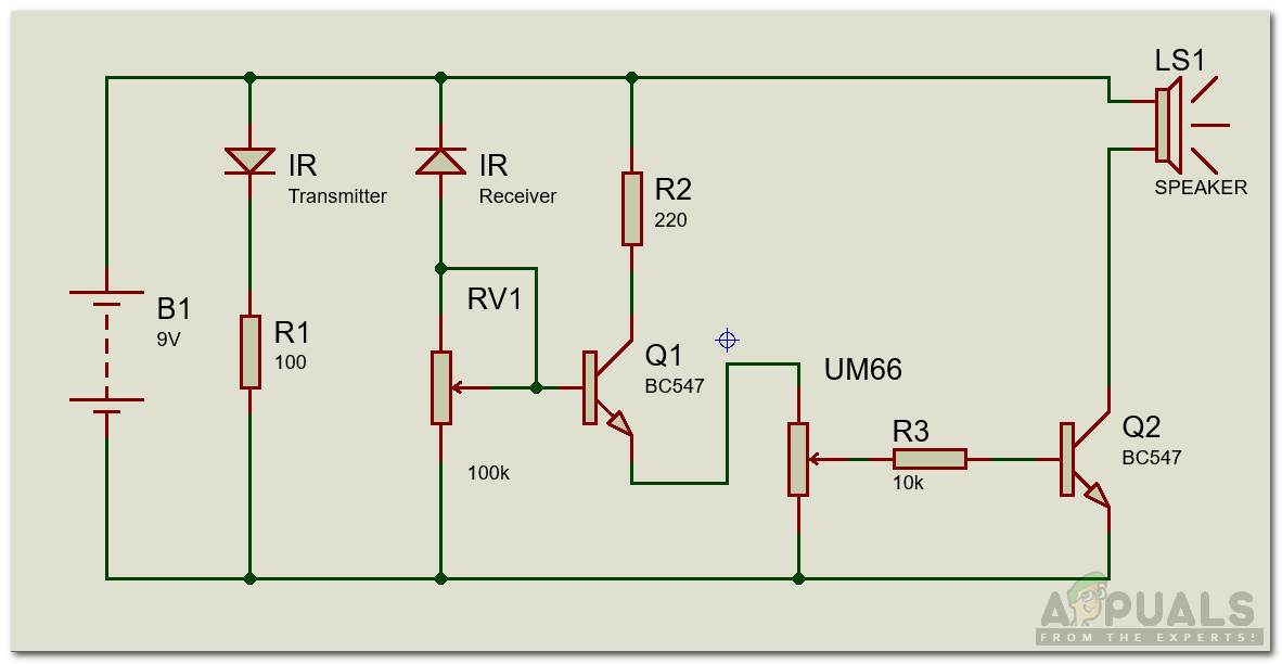
Step 3: Designing Circuit On Proteus.
As we have collected the components before attaching them on the vero board we will test them on software and will check whether they are working properly or not by running the simulation. The transistor used here has three legs and people don’t connect those in the circuit accurately. So, for their ease, the circuit is designed on software.
Step 4: Assembling The Hardware.
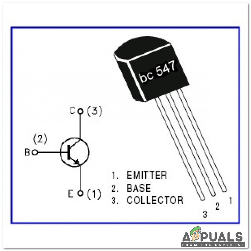
As we have run the simulation no we are in a position to make a prototype. While soldering the components on the Vero board pay special attention towards BC 547 transistor and UM 66 IC. UM 66 IC is used to create a melody when someone comes in front of 100k preset. BC 547 has three legs known as Emitter, Base, and Collector. The collector is connected to a 220-ohm resistor, the base is connected to a 100k preset and emitter is connected to UM 66 IC. The pin configuration of the BC 547 transistor is shown below :
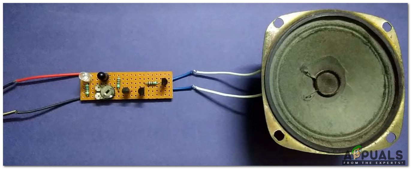
Now we will solder the components on the Vero board with the help of soldering Iron and final look of the board from the front side as well as the backside is shown as under :
- Front View:
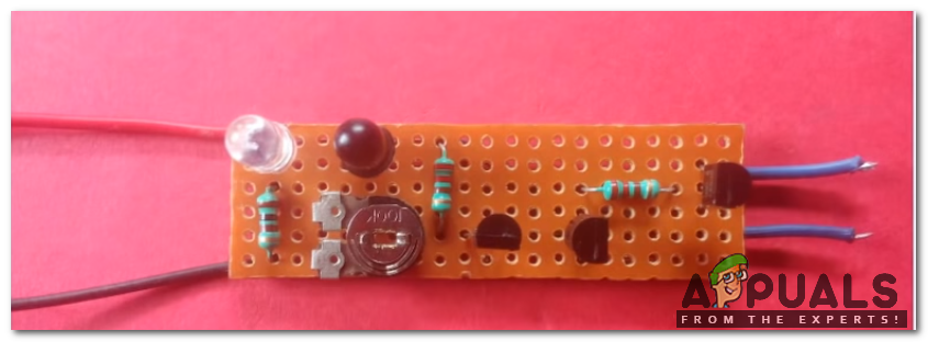
Front View Of Vero Board - Back View:
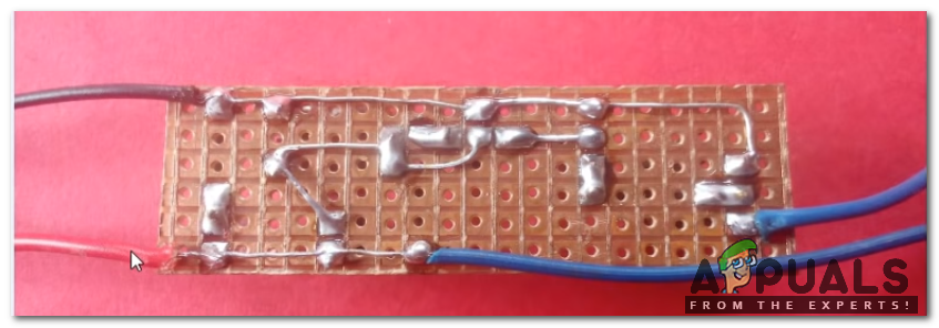
Back View Of Vero Board
As we have designed the prototype we can fix it at the front door of our house and it’s better to place it in a box so, that it is not affected by rain or extreme weather conditions. We will provide a power supply using a 9V DC adapter with filtered and regulated output. If the 9V adapter with regulated output is not available, then we will use a 12V unregulated DC adapter with a 7809 voltage regulator. The bell will sound automatically when someone comes in front of your door.


