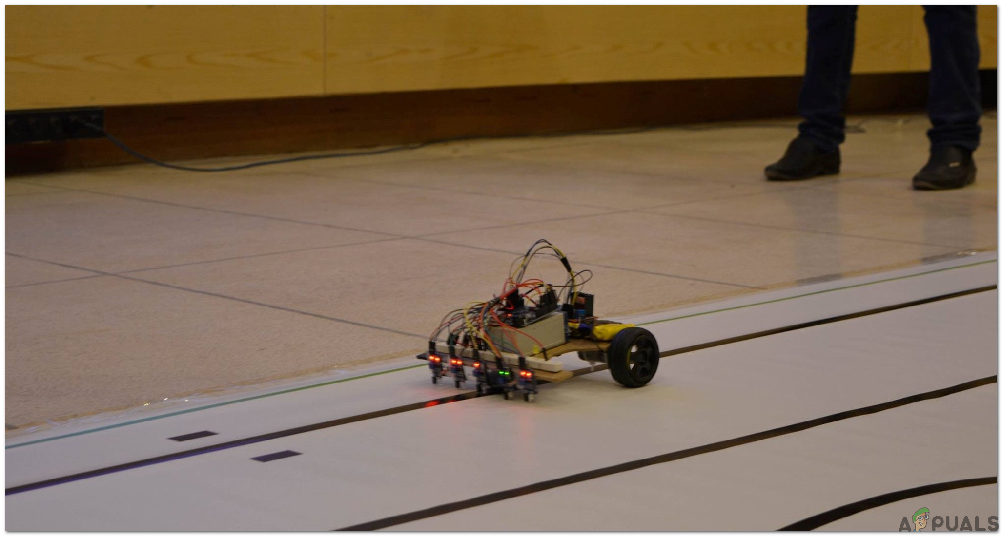
How To Move Dishes Around Your Kitchen Shelf Using A Robot?
If you’re looking for a way to dramatically boost the charm and functionality of your kitchen, consider minimizing the human effort there. The human effort can be minimized by making a domestic robot that will be present in the kitchen and it will carry dirty utensils towards the sink and stop there. When the person unloads the utensils from the robot it will return and bring more of them. Sometimes in big kitchens, the washing sink is not so close to the cabinets so, the robot will take the dishes from one place of the shelf towards the other. A path for the robot will be made on the shelf using the Black tape. The robot will use two infrared proximity sensors to detect the path and based on input received from the sensors, the Arduino will direct the motors to move with the help of a motor driver.
How To Connect All The Necessary Peripherals In Making Of A Domestic Robot?
Now, we need to gather the components required and start making the robot.
Step 1: Components Used
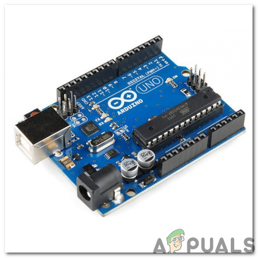
- Arduino Uno
- IR Sensor (x5)
- No products found.
- DC Motors
- No products found.
- Black Tape
- No products found.
- DC Battery
- No products found.
- Glue Gun
- Screw driver set
Step 2: Studying The Components
As we have already made a list of components, let us move a step ahead and go through a brief study of the working of each component.
The Arduino UNO is a microcontroller board which comprises of a microchip ATMega 328P and is developed by Arduino.cc. This board has a set of digital and analog data pins that can be interfaced with other expansion boards or circuits. This board has 14 Digital pins, 6 Analog pins, and programmable with the Arduino IDE (Integrated Development Environment) via a type B USB cable. It requires 5V to power ON and a C Code to operate.
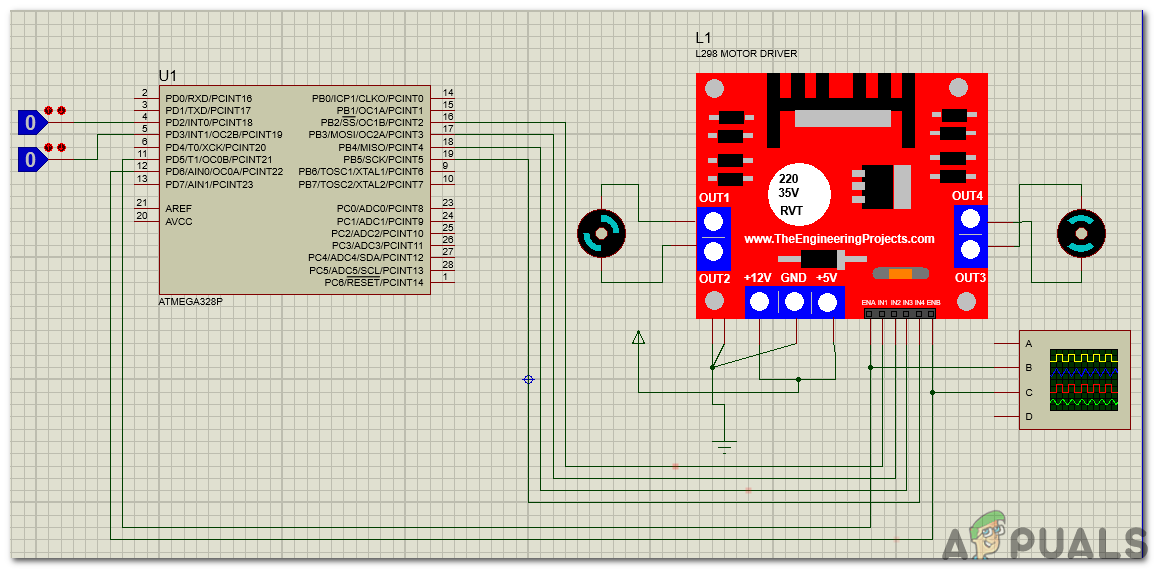
L298N Motor Driver is used to operate DC Motors. The L298N is a dual H-Bridge motor driver that allows speed and direction control of two DC motors at the same time. The module can drive DC motors that have voltages between 5 and 35V, with peak current up to 2A. It depends on the voltage that is used at the motors VCC terminal. In our project, the 5V pin will be used as input as we need to connect it to a 5V power supply for the IC to work properly. The circuit diagram of the L298N motor driver with the DC motors connected is shown below for understanding the mechanism of the L298N motor driver. For the demonstration, the input is given from the Logic State instead of IR sensors.
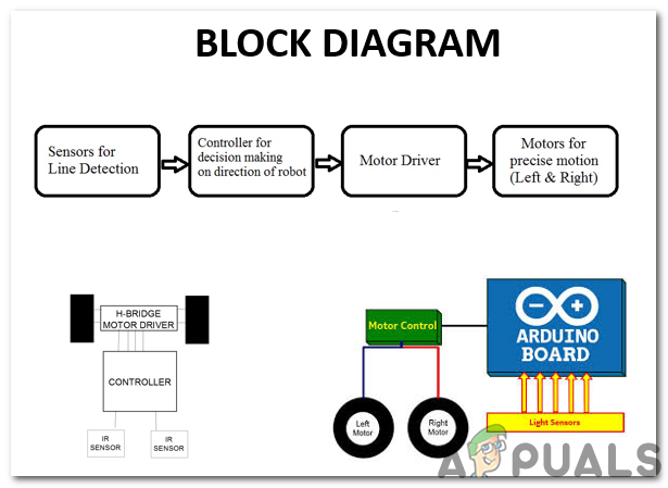
Step 3: Understanding The Block Diagram And Working Principle
Firstly, we will go through the block diagram, understand the working principle and then move towards assembling the hardware components.
The sensors that we will use are digital and they can give the output either 0 or 1. These sensors that we have purchased are giving 1 on white surfaces and 0 on the black surfaces. The sensors that we purchase give random values, sometimes they give 0 on the white surfaces and 1 on the black surfaces. We will use five sensors in this robot There are four conditions in the code for five sensors.
- Forward On The Line: When the middle sensor is on the black surface and the rest of the sensors are on the white surface, the forward condition will execute and the robot will move straight forward. If we start from Sensor1 and proceed till Sensor5, the value that each of the sensors will be giving respectively is (1 1 0 1 1).
- Sharp Right Turn: When the Sensor 1 and Sensor 2 are on the white surface and the rest of the sensors are on the black surface, the sharp right turn condition will execute and the robot will turn sharp right. If we start from Sensor1 and proceed till Sensor5, the value that each of the sensors will be giving respectively is (1 1 0 0 0).
- Sharp Left Turn: When the Sensor 4 and Sensor 5 are on the white surface and the rest of the sensors are on the black surface, the sharp left turn condition will execute and the robot will turn sharp left. If we start from Sensor1 and proceed till Sensor5, the value that each of the sensors will be giving respectively is (0 0 0 1 1).
- Stop: When all of the five sensors are on the black surface the robot will stop and motors will turn OFF. This point with five black surfaces will be near the sink so that the dishwasher could unload the plates from the robot for washing.
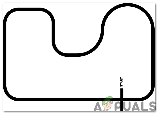
We will make a path on the kitchen shelf using black tape and that path will end near the sink, so the robot will stop near the sink and the dishwasher will unload the plates and then the robot will move towards the path and search for the utensils again.
Step 4: Getting Started With Arduino
If you are not familiar with Arduino IDE before, don’t worry because below, you can see clear steps of burning code on the microcontroller board using Arduino IDE. You can download the latest version of Arduino IDE from here and follow the steps below:
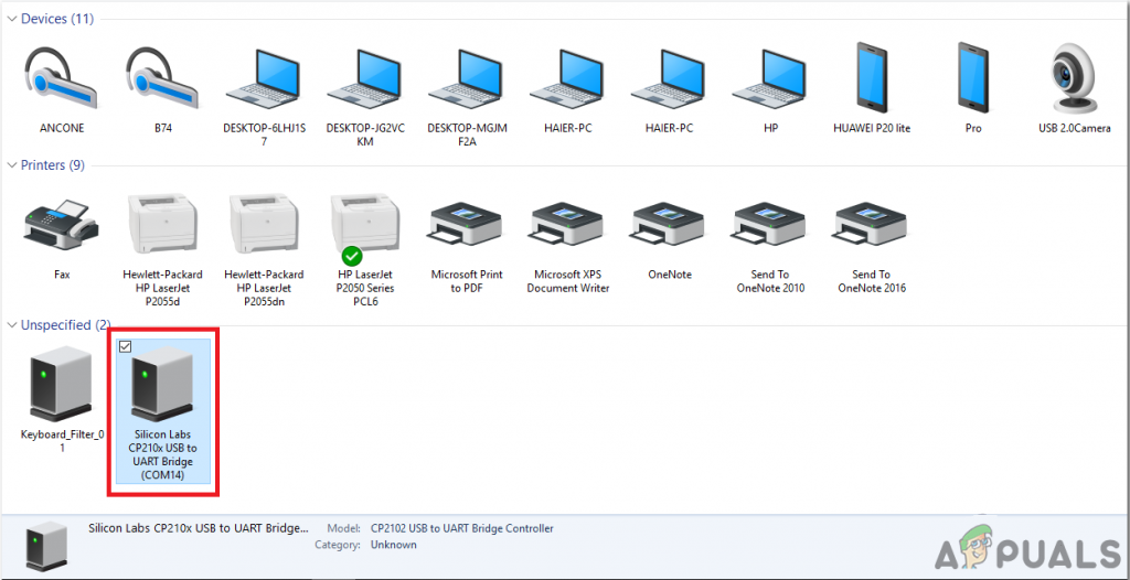
- When the Arduino board is connected to your PC, open “Control panel” and click on “Hardware and Sound”. Then click on “Devices and Printers”. Find the name of the port to which your Arduino board is connected. In my case it is “COM14” but it may be different on your PC.
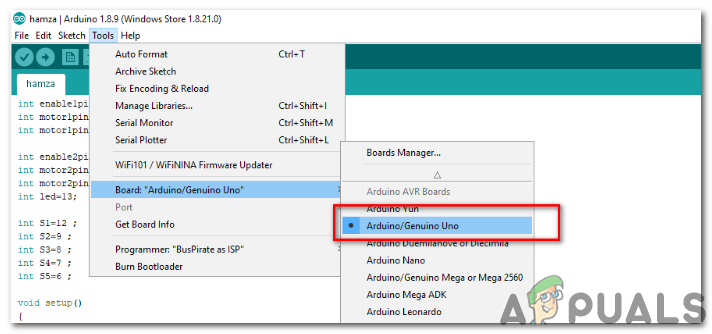
Finding Port - Now open the Arduino IDE. From Tools, set the Arduino board to Arduino / Genuino UNO.
Setting Board - From the same Tool menu, set the port number that you saw in the control panel.
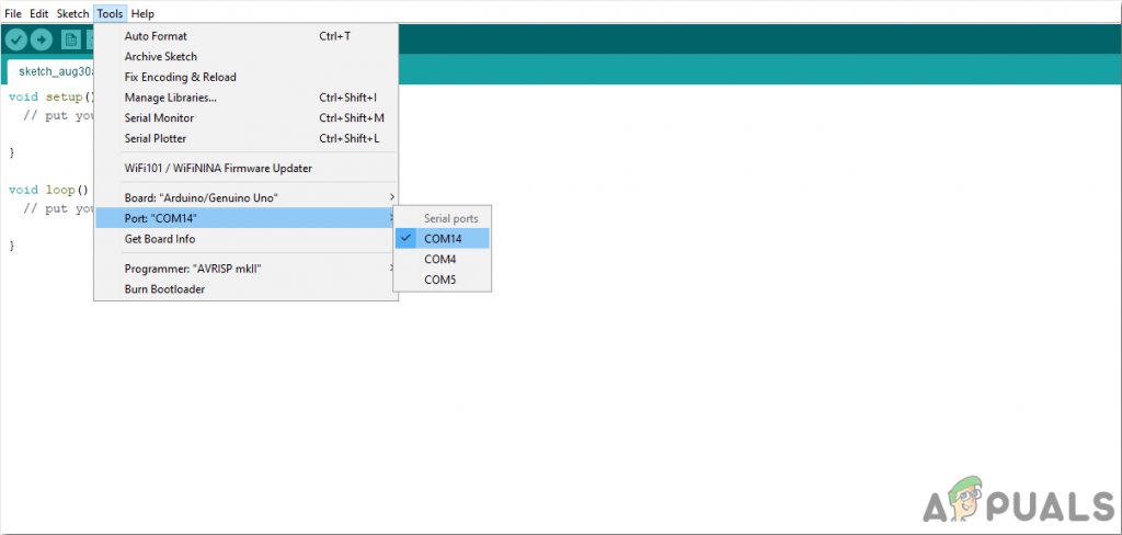
Setting Port - Download the code attached below and copy it to your IDE. To upload the code, click on the upload button.
You can download the code from Here
Step 5: Understanding The Code
The code is very simple. It is explained briefly below:
- At the start of the code the sensor pins are initialized and along with that, the pins for the Motor Driver L298N are also initialized.
int enable1pin=10;  //Initializing PWM Pin For Analog Input For Motor 1
int motor1pin1=2;   //Initializing Positive Pin For Motor 1
int motor1pin2=3;   //Initializing Negative Pin For Motor 1

int enable2pin=11;  //Initializing PWM Pin For Analog Input For Motor 2
int motor2pin1=4;   //Initializing Positive Pin For Motor 2
int motor2pin2=5;   //Initializing Negative Pin For Motor 2

int S1=12 ;  //Initializing Pin 12 For Sensor 1
int S2=9 ;   //Initializing Pin 9 For Sensor 2
int S3=8 ;   //Initializing Pin 8 For Sensor 3
int S4=7 ;   //Initializing Pin 7 For Sensor 4
int S5=6 ;   //Initializing Pin 6 For Sensor 5
- void setup() is a function that is used to set the pins as INPUT or OUTPUT. It also sets the baud rate of the Arduino. Baud rate is the speed at which the microcontroller board communicates with the other components attached.
{ pinMode(enable1pin, OUTPUT); //Enabling PWM for Motor 1 pinMode(enable2pin, OUTPUT); //Enabling PWM for Motor 2 pinMode(motor1pin1, OUTPUT); //Setting motor1 pin1 as output pinMode(motor1pin2, OUTPUT); //Setting motor1 pin2 as output pinMode(motor2pin1, OUTPUT); //Setting motor2 pin1 as output pinMode(motor2pin2, OUTPUT); //Setting motor2 pin2 as output pinMode(S1, INPUT); //Setting sensor1 as input pinMode(S2, INPUT); //Setting sensor2 as input pinMode(S3, INPUT); //Setting sensor3 as input pinMode(S4, INPUT); //Setting sensor4 as input pinMode(S5, INPUT); //Setting sensor5 as input Serial.begin(9600); //Setting the baud rate } - void loop() is a function that runs again and again in a cycle. In this loop, we give instructions to the Arduino UNO what operations to carry out. The full speed of the motors is 255 and both motors have different speed. So, if we want to move the robot forward, turn right etc we need to adjust the speed of the motors. We have used analog pins in the code because we want to vary the speed of the two motors in different conditions. You can adjust the speed of your motors on your own.
void loop()
{
if(!(digitalRead(S1))&&!(digitalRead(S2))&&(digitalRead(S3))&&!(digitalRead(S4))&&!(digitalRead(S5))) //Forward on the line
{
analogWrite(enable1pin, 61);  //Motor 1 speed
analogWrite(enable2pin, 63);  //Motor 2 speed

digitalWrite(motor1pin1, HIGH); //Motor 1 pin 1 set to High
digitalWrite(motor1pin2, LOW);  //Motor 1 pin 2 set to Low
digitalWrite(motor2pin1, HIGH); //Motor 2 pin 1 set to High
digitalWrite(motor2pin2, LOW);  //Motor 2 pin 2 set to Low
}

if(!(digitalRead(S1))&&!(digitalRead(S2))&&(digitalRead(S3))&&(digitalRead(S4))&&(digitalRead(S5))) // Sharp Right Turn
{
analogWrite(enable1pin, 60);  //Motor 1 speed
analogWrite(enable2pin, 80);  //Motor 2 speed

digitalWrite(motor1pin1, HIGH);  //Motor 1 pin 1 set to High
digitalWrite(motor1pin2, LOW);   //Motor 1 pin 2 set to Low
digitalWrite(motor2pin1, LOW);   //Motor 2 pin 1 set to Low
digitalWrite(motor2pin2, LOW);   //Motor 2 pin 2 set to Low
}

if((digitalRead(S1))&&(digitalRead(S2))&&(digitalRead(S3))&&!(digitalRead(S4))&&!(digitalRead(S5))) // Sharp Left Turn
{
analogWrite(enable1pin, 80);  //Motor 1 speed
analogWrite(enable2pin, 65);  //Motor 2 speed

digitalWrite(motor1pin1, LOW);  //Motor 1 pin 1 set to Low
digitalWrite(motor1pin2, LOW);  //Motor 1 pin 2 set to Low
digitalWrite(motor2pin1, HIGH); //Motor 2 pin 1 set to High
digitalWrite(motor2pin2, LOW);  //Motor 2 pin 2 set to Low
}

if((digitalRead(S1))&&(digitalRead(S2))&&(digitalRead(S3))&&(digitalRead(S4))&&(digitalRead(S5))) // stop
{
analogWrite(enable1pin, 0);  //Motor 1 speed
analogWrite(enable2pin, 0);  //Motor 2 speed

digitalWrite(motor1pin1, LOW);  //Motor 1 pin 1 set to Low
digitalWrite(motor1pin2, LOW);  //Motor 1 pin 2 set to Low
digitalWrite(motor2pin1, LOW);  //Motor 2 pin 1 set to Low
digitalWrite(motor2pin2, LOW);  //Motor 2 pin 2 set to Low
}
}
Applications
- Industrial Applications: These robots can be used as automated equipment carriers in industries replacing traditional conveyor belts.
- Domestic applications: These can also be used at homes for domestic purposes like floor cleaning, kitchen work, etc.
- Guidance applications: These robots can be used in public places like shopping malls, food courts, museums etc to provide path guidance


