How to Measure Heart Rate using Heart Beat Sensor?
Heart rate or pulse rate is the most important parameter that is measured in the field of medicine. There are two ways in which the heart rate can be measured. One is to manually check the wrist by using a stethoscope and guessing the heart rate, the other method is to use a heart rate sensor. A heart rate sensor gets some readings of the pulse and sends an electrical signal to the microcontroller, these readings are then calculated and the exact pulse rate is displayed.
How a Heart Rate Sensor Measures the Pulse rate?
As we know what we are going to do, so let’s start working on this project.
Step 1: Collecting the Components
Making a list of components and studying the working of those components is the best approach before starting any project. Following are the components that will be used in our project:
- No products found.
- No products found.
- No products found.
- No products found.
- No products found.
Step 2: Knowing the Components Used
As we have the list of apparatus that we are going to use. Now let us see how these components work.
Arduino Uno is a microcontroller board that is used to control various circuits. It uses a C code that gives it the instructions to perform a task. Other substitutes of this microcontroller board available in the market are Arduino Nano, Node MCU, ESP32, etc.
SEN-11574 is a plug and play pulse rate sensor that is integrated with Arduino. It has two sides. On one side, a led is placed which emits light. This led should be placed directly on the top of a vein. As we know that the volume of blood in the vein is greater when the heart pumps, so when there is more blood in the vein, more light will be reflected to the sensor. This change in the light received by the sensor is analyzed over time and the heart rate is measured. On the other side of the sensor, a circuit is present which is responsible for the amplification and noise removing of the received signal.
Step 3: Assembling the components
- As we know that the skin is of a human body, is moist or oily sometimes. This could result in the short circuit of the sensor which gives false measurements. It is better to apply a layer of a vinyl sticker on the LED side of the sensor to prevent it from the moist on the skin.
- After doing this, take a piece of black vector tape and paste it on the other side of the sensor. This will prevent light from the surroundings to interrupt the light of the sensors.
- Now, connect the Vcc and ground pin of the sensor to Arduino and the analog pin of the sensor to A0 of Arduino.
All the apparatus is now set and ready to be used. We will put the sensor directly on the vein, either on the finger or the ear to measure the heart rate.
Step 4: Getting Started with Arduino
If you haven’t worked on Arduino IDE before, don’t worry because the procedure to burn a code on the microcontroller board using Arduino IDE is given below.
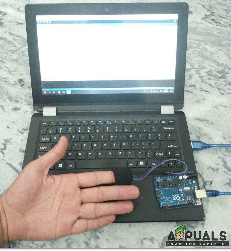
- After connecting your Arduino board to your PC, go to Control Panel > Hardware and Sound > Devices and Printers to check the name of the port to which Arduino is connected. It is different on different computers.
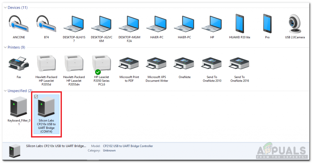
Finding Port - Open the Arduino IDE and set the board as Arduino/Genuino UNO.
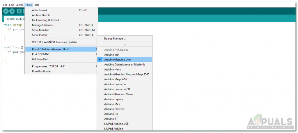
Setting Board - Now set the port that you observed before in control panel.
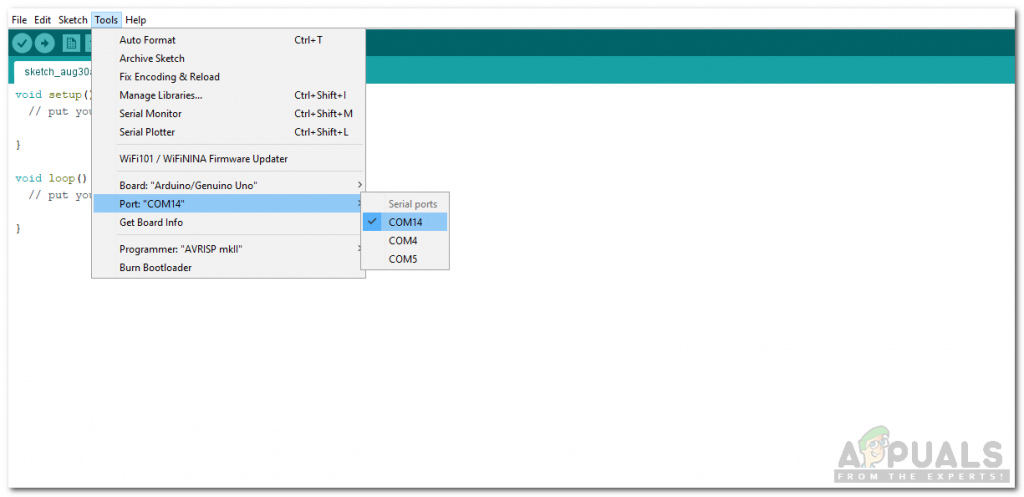
Setting Port - Download the code given below and open it. Burn the code on your Microcontroller board by clicking the Upload button.
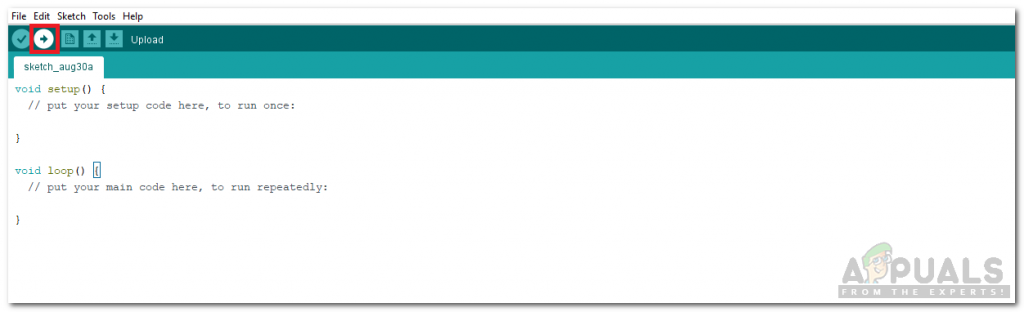
Upload
Click here to download the code.
Step 5: Code
The code to measure the pulse rate is a little bit lengthy and complicated. Some part of the code is explained below.
1. In the start, all the pins that will be used are defined. All the variables that will be used in different functions and the interrupt service routine (ISR).
2. void setup() is a function in which Pins are defined to be used as INPUT or OUTPUT. baud rate is also set in this function. Baud rate is the speed by which the microcontroller communicates with other components. ISR is also called in this function.
3. void loop() is a function that runs continuously in a cycle. Here, pulse rate is found and it decides when to fade the led when a heartbeat is found.
void loop() {
serialOutput() ;
if (QS == true) { // A Heartbeat Was Found
// BPM and IBI have been Determined
// Quantified Self "QS" true when arduino finds a heartbeat
fadeRate = 255; // Makes the LED Fade Effect Happen
// Set 'fadeRate' Variable to 255 to fade LED with pulse
serialOutputWhenBeatHappens(); // A Beat Happened, Output that to serial.
QS = false; // reset the Quantified Self flag for next time
}
ledFadeToBeat(); // Makes the LED Fade Effect Happen
delay(20); // take a break
}
4. void serialOutput() is a function which decides how to show output on the serial monitor.
void serialOutput(){
switch(outputType){
case PROCESSING_VISUALIZER:
sendDataToSerial('S', Signal); // goes to sendDataToSerial function
break;
case SERIAL_PLOTTER: // open the Arduino Serial Plotter to visualize these data
Serial.print(BPM);
Serial.print(",");
Serial.print(IBI);
Serial.print(",");
Serial.println(Signal);
break;
default:
break;
}
}
5. ISR is an interrupt that is generated by the hardware and sent to the CPU for processing. when the interrupt is generated, the process, which is already going on stops and the interrupt is processed. after the interrupt is processed, the previous process resumes.
void interruptSetup() { // CHECK OUT THE Timer_Interrupt_Notes TAB FOR MORE ON INTERRUPTS
#ifndef ESP32
// Initializes Timer2 to throw an interrupt every 2mS.
TCCR2A = 0x02; // DISABLE PWM ON DIGITAL PINS 3 AND 11, AND GO INTO CTC MODE
TCCR2B = 0x06; // DON'T FORCE COMPARE, 256 PRESCALER
OCR2A = 0X7C; // SET THE TOP OF THE COUNT TO 124 FOR 500Hz SAMPLE RATE
TIMSK2 = 0x02; // ENABLE INTERRUPT ON MATCH BETWEEN TIMER2 AND OCR2A
sei(); // MAKE SURE GLOBAL INTERRUPTS ARE ENABLED
// Create semaphore to inform us when the timer has fired
#else
timerSemaphore = xSemaphoreCreateBinary();

// Use 1st timer of 4 (counted from zero).
// Set 80 divider for prescaler (see ESP32 Technical Reference Manual for more
// info).
timer = timerBegin(0, 80, true);

// Attach onTimer function to our timer.
timerAttachInterrupt(timer, &onTimer, true);

// Set alarm to call onTimer function every second (value in microseconds).
// Repeat the alarm (third parameter)
timerAlarmWrite(timer, 2000, true);

// Start an alarm
timerAlarmEnable(timer);
#endif
}
Applications:
Now as we know how to measure the Pulse rate using a heart rate sensor. Now we can use it to make different projects for example
- Health bands.
- Anxiety Monitor.
- Sleep Tracking.
- Remote patient monitoring/alarm system.
- Advanced gaming consoles


Very impressive article