How To Make IOT Smart Garage Opener Using Raspberry Pi?
In this era where the latest technology keeps us invading day by day internet of things (IoT), it has recently emerged as a state-of-the-art approach for automating electronic devices and hence reducing human interference to a great extent. A lot of technologies support wireless control of devices like Radio Frequency Identification (RFID), Bluetooth, Wifi, etc. In this project, we will make a Smart Garage Door Opener Using Raspberry Pi. The raspberry pi webserver will be created to open and close the garage door using your smartphone.
How To Setup Raspberry Pi And Other Hardware Components?
As we have understood the basic aim of this project, now let’s move a step further towards collecting the components and assembling them.
Step 1: Components Required
- No products found.
- No products found.
- Jumper Wires – Female to Female
- Ethernet Cable
- 12V AC Bulb
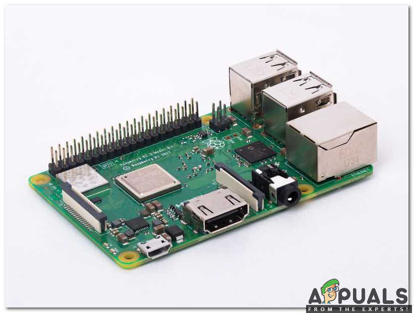
Step 2: Selecting the Raspberry Pi Model
Several models of raspberry pi are available in the market. Except for raspberry pi zero, any model can be preferred. This is because on Pi zero setting up a network is a very tiring job. The latest models like 3A+, 3B+ or 4 can be purchased. The new Raspberry Pi 3 is the quickest and most dominant gadget the Raspberry Pi Foundation has released to date. So, in this project, we will use the Raspberry Pi 3B+.
Step 3: Choosing The Operating System
Firstly, we will need an SD card with an appropriate operating system. When picking the OS, nowadays there are various alternatives, from “conventional” Raspbian to devoted media working frameworks, and even Windows 10 IoT. Raspbian is preferred because it comes with over 35000 packages. Raspbian is a community project under active development, with an emphasis on improving the stability and performance of as many Debian packages as possible.
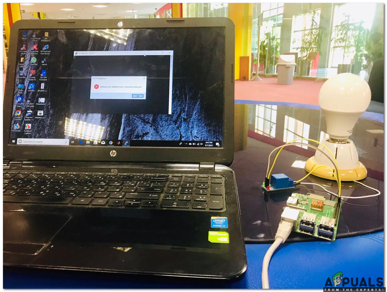
Step 4: Interfacing Raspberry With Laptop
External monitor or LCD using HDMI cable can be used as a display to connect with Raspberry Pi. If anyone doesn’t have LCD he/she can use a laptop to connect Pi but some configurations will need to be done for connectivity. We will use a Secure Shell (SSH) client known as Putty to connect Pi using a laptop. Interfacing is explained in steps mentioned below :
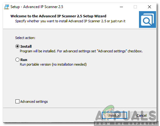
- Installing Advanced IP Scanner: Advanced IP Scanner is a tool that is used to detect IPs that are assigned to the devices by your Wifi router. We will install this software by clicking Here
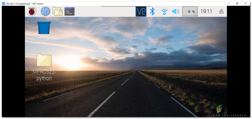
- Detecting IP Assigned To Raspberry Pi: Now, we will check the static IP that is assigned to our Raspberry Pi.
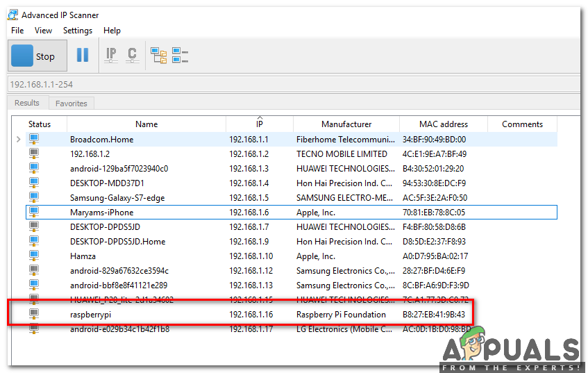
Checking The IP Address The IP address assigned to our Raspberry Pi is 192.168.1.16. Note this IP address because it will be needed in further configurations. Note: Every person will be assigned a different IP address depending upon the Wifi router.
- Download Putty And Enter IP Address In It: Putty is an SSH client and it is open-source software that is available with source code. It can be downloaded from Here. After downloading Putty open it and enter the static IP address “192.168.1.16” to connect to the laptop.
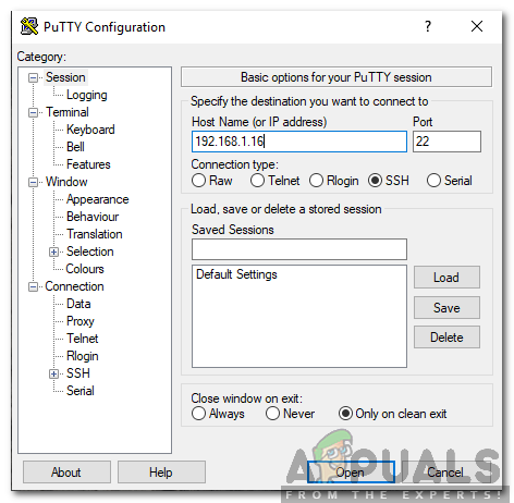
Configuring Putty - Logging In: After entering the IP address the screen will appear and it will ask for username and password. The default username is “pi” and password is “raspberry“. We can change login details too if we want.
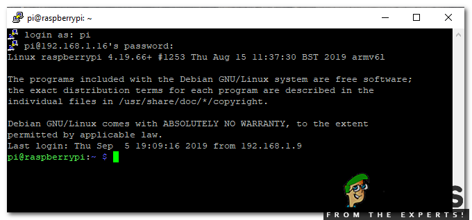
Logged In
Step 5: Circuit Diagram
Now as we know how the components work let’s go ahead and assemble these components and make a circuit as shown below.
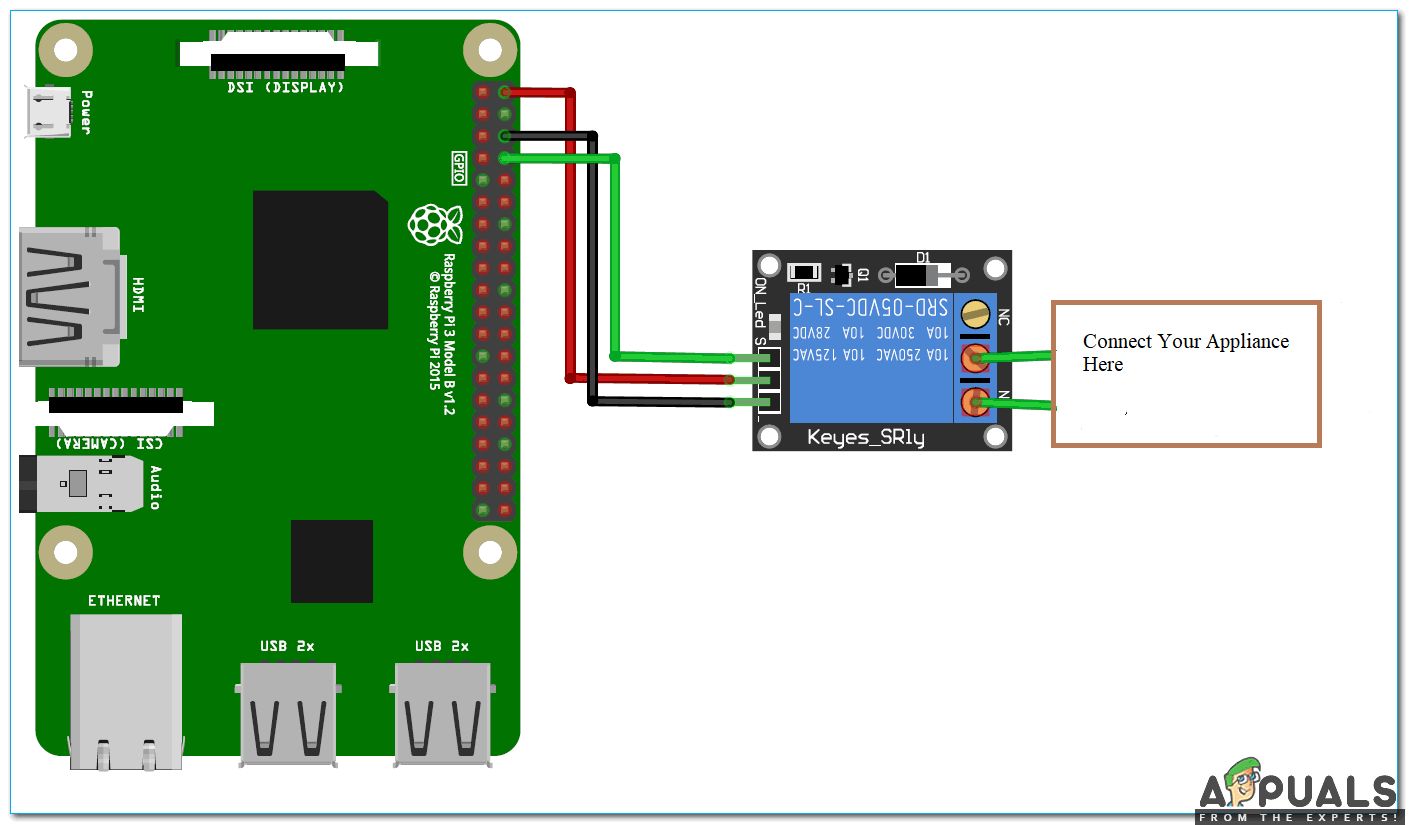
Relay is powered by 5 V of Raspberry Pi and General Purpose Input Output (GPIO-14), is connected to the IN of the relay. It will tell the relay when to switch ON and OFF. We have connected 12V AC bulb to the output of the relay so that when the garage door is opened bulb is turned ON and when the garage door is closed the bulb is turned OFF.
Step 6: Flask Setup In Pi For Controlling Garage Door
We will create a Web server using Flask which will pave the way for sending commands from Webpage to Raspberry Pi to control our prototype over the network. Flask enables us to run our python contents through a website page and we can send and get information from Raspberry Pi to the internet browser and the other way around. It is a microframework for Python. This tool is Unicode based having built-in development server and debugger, integrated unit testing support, support for secure cookies and its easy to use, these things make it valuable for the specialist. For installing Flask on your Raspberry Pi type the following commands:
sudo apt-get update
sudo apt-get install python-pip python-flask
Now, run pip command to install Flask and it’s dependencies :
sudo pip install flask
Step 7: Create A Python Script For Door Opener
This script will cooperate with our Raspberry Pi GPIOs and sets up the webserver. It is the main script for our project. Python script will be explained in the parts below:
Firstly, we will make a folder. All other required folders should be in this folder only. Run below commands to make a folder and then create a python file named app.py inside this folder:
mkdir garage_door
cd garage_door
nano app.py
The above commands will open the Nano editor where will write the script below. Include important libraries:
import RPi.GPIO as GPIO
from flask import Flask, render_template, request
app = Flask(__name__, static_url_path='/static')
Now, create a dictionary as pins to store the PIN, name, and pin state. You can utilize more than one pin as per your need:
pins =
{
   14 : {'name' : 'Garage Door', 'state' : GPIO.LOW}
}
Then, set the pin to output and set it to low initially:
for pin in pins:
   GPIO.setup(pin, GPIO.OUT)
   GPIO.output(pin, GPIO.LOW)
We will make the function to read pin state and store this state in a variable:
@app.route("/")
def main():
   for pin in pins:
      pins[pin]['state'] = GPIO.input(pin)
..
We will pass this data to our HTML page so, that we can control the input button state:
return render_template('main.html', **templateData) For handling requests from URL make a function with PIN and action in it:
@app.route("/<changePin>/<action>", methods=['GET', 'POST'])
def action(changePin, action):
After that convert pin from the URL into an integer;
changePin = int(changePin)
If the action part of the URL is “open,” at that point do the following:
if action == "open":
      GPIO.output(changePin, GPIO.HIGH)
   if action == "close":
      GPIO.output(changePin, GPIO.LOW)
I will attach the complete script at the end and if anybody wants to copy that he/she can do that by pressing ctrl+x and then pressing Enter. Now we are done with the python script and we will make an HTML page to interact with the python script.
Step 8: Creating HTML Page For Raspberry Pi Server
We will make changes in the garage_door folder that we created previously. We will create another folder named templates and inside this folder make a .html files using the following commands:
mkdir templates
cd templates
nano main.html

Now, open the nano text editor and write the HTML code. We can edit <head> part of the page and modify it according to our own choice. We have used the third party CSS scheme using the link tag. The complete code is given below:
Click here to download the HTML code to create a web page.
Step 9: Creating A Button For Opening And Closing The Door
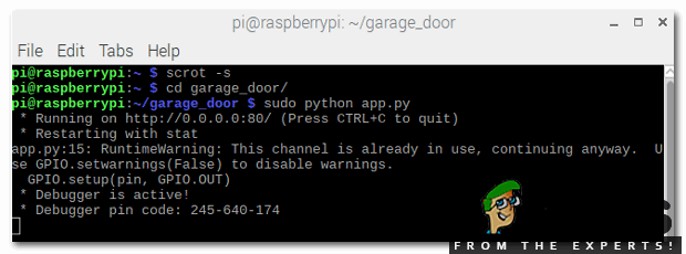
We will have to assign a state to open and close the button. That button will send and fetch the GPIO state from the python script. As we have completed the above HTML code now we can use it in the editor and save it and finally our web server is ready to launch. Open the terminal and navigate to garage_door folder and run the below command mentioned below:
sudo python app.py
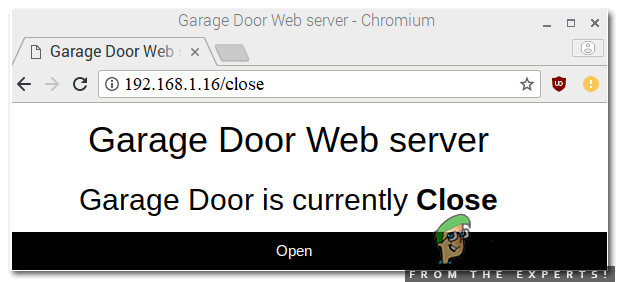
Open the browser and enter the IP address of Raspberry Pi and press Enter. This type of page will be shown:
Step 10: Setting Up The Hardware
As we are done with the software setup now let’s move a step ahead and assemble the hardware. make sure that the relay module is connected to the Raspberry Pi. For testing press open button to switch ON the relay and close button to switch OFF the relay. As soon as the relay is turned on the AC bulb lights up and we come to know that the gate is open and when the bulb is powered off we come to know that the gate is closed. To stop the server press ctrl+c.
Click here to download the code to setup Hardware.


Thanks for the idea