How to Make Curtain Opener and Closer Circuit?
In the present century, if we look around in the surrounding, we will find that most of the things that operate on electricity are made automated so that less human effort is required. Engineers are trying to make devices that can be integrated with mechanical systems that bring them to operate with just a press of a button. We see that in our homes and offices, curtains on the windows, doors and terrace etc, are to be pushed by hand to open and close them. This requires a little human effort because we have to get up, move to the window and push the curtains both of the times while closing and opening them. This effort can be minimized by integrating an electrical circuit with it.
Many curtain opener circuits are available in the market. They are very efficient but very costly. The main aim of this article is to design a circuit that will be used to open or close the curtains just by a press of a button. This solution will be as efficient as the circuit available in the market and will be very low in cost. We will use two ICs and a stepper motor to perform this task.
How To Open And Close The Circuit Automatically?
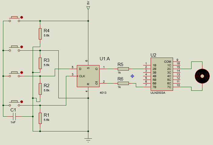
The heart of this project is two ICs names as CD4013 and ULN2003. These ICs are used with a few more components that are easily available in the market to make a complete circuit. There are two D-type flip-flops which are self governer, located on this CD4013 IC. These flip-flops exist in one of the two states i.e. 0 or 1. The task of these flip-flops is to store information. Both of the modules have a pinout. These pins are names as Data, Clock Input, Set, Reset, and a Couple of output pins.
Step 1: Collecting The Components (Hardware)
The best approach to start any project is to make a list of components and going through a brief study of these components because no one will want to stick in the middle of a project just because of a missing component. A list of components that we are going to use in this project is given below:
- No products found.
- No products found.
- No products found.
- 5.6k-ohm Resistor
- 1uF Capacitor
- No products found.
- Connecting wires
- No products found.
- 9V Battery
- No products found.
Step 2: Gathering The Components (Software)
- Proteus 8 Professional (Can be downloaded from Here)
After downloading the Proteus 8 Professional, design the circuit on it. I have included software simulations here so that it may be convenient for beginners to design the circuit and make appropriate connections on the hardware.
Step 3: Working of a D Flip-Flop
A D-type flip-flop is a flip-flop which has its one input as a DATA input. It is named as Delayed (D) flip flop because when it is given the input at input pin, the data will appear at the output pin after some time when the clock ends. In this way, the data is transferred from the input side to the output side after a required delay. This device is used as a delay device and is also commonly known as a latch.
1-bit binary information is stored in its clock input. The input line controls the flip-flop in this clock. This is used to decide if the data is dropped or recognized. Most o the time, a clock signal is the input. If a Binary High means a logic 1 is sent as a clock input, the flip flop will store the data on the data line. The data input will be simply followed by the normal output, as long as the state of the clock line is HIGH. The data input line will be recognized as soon as the clock line becomes binary low or logic 0. This means that the bit that was previously stored in the flip-flop is retained. When the clock is low, it will be ignored.
Step 4: Design of the Circuit
CD4013 is an integrated circuit that comes in a 14-pin dual inline package. Its pin1, pin2, pin13, and pin12 all are complementary output but in both of the pairs, one pin is inverse of the other. For example, if [in1 shows 1, then pin2 will show 0. Similarly is the case of the other pair of pin12 and pin13. The Data pins of this IC are pin5 and pin9 and generally, one of the outputs is connected to them. in our circuit pn5 off the IC is connected to the inverting output. Pin3 and Pin11 are named as the clock input of the IC. the D type flip-flop works when these pins receive the input signal to provide the input to these pins, an Astable multivibrator, made by a transistor configuration, can be used or the Logic gates like NOR gate can be used to perform the same task. We are using a transistor to provide the input to these pins. Pin4, Pin6, and Pin8, Pin10 is the set and reset pins of the IC respectively. The output will be received if any one of these pins goes high. For protection, these pins connected to the ground through a resistor of high value. Pin14 is the supply pin of the IC and Pin7 is the ground pin of the IC. The main supply is connected to the pin14 and it should not be greater than 15V. If it is greater than 15V, the IC may burn away. The negative terminal of the battery is connected to the pin7 of the IC.
In ULN2003, pin1 to pin7 is the seven input pins of the Darlington configurations. each pin is connected to the base of the transistor and it can be switched just by applying 5V to it. Pin8 is the ground pin of the IC and it is directly connected to the negative terminal of the battery. The test pin of this IC is pin9. pin10 to pin16 are the output pins of this IC.
Step 5: Assembling The Components
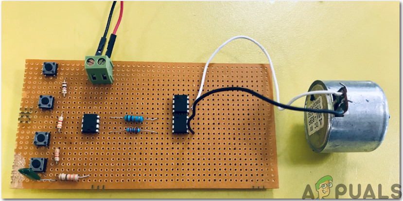
Now, as we know the main connections and also the complete circuit of our project, let us move ahead and start making the hardware of our project. One thing must be kept in mind that the circuit must be compact and the components must be placed so close.
- Take a Veroboard and rub its side with the copper coating with a scraper paper.
- Now Place the components carefully and close enough so that the size of the circuit does not become very big.
- Carefully make the connections using solder iron. If any mistake is made while making the connections, try to desolder the connection and solder the connection again properly, but in the end, the connection must be tight.
- Once all the connections are made, carry out a continuity test. In electronics, the continuity test is the checking of an electric circuit to check whether current flow in the desired path (that it is in certainty a total circuit). A continuity test is performed by setting a little voltage (wired in arrangement with a LED or commotion creating part, for example, a piezoelectric speaker) over the picked way.
- If the continuity test passes, it means that the circuit is adequately made as desired. It is now ready to be tested.
- Connect the battery to the circuit.
The circuit will look like the image below:
Step 6: Circuit Operations
Now as the whole circuit is made, let us test it and see if it operates as required or not.
- Press the switch S1. By doing so, pin6 of the IC1 will be supplied voltage. As this happens, pin6 will make the state of pin1 of the IC1 HIGH with it.
- When this happens, the pin2 of the IC2 also gets HIGH. So, this will result in the clockwise movement of the geared motor because it is connected to this pin of the IC2. This will start opening the curtain.
- Now, if the curtain opens at the full limit or if you want to stop it in the middle of its way, you just need to push the switch S2. The switch S2 is connected to the Pin4 of the IC1. The purpose of this Reset pin here is to stop the rotation of the motor when the curtain is to be stopped by resetting the state of IC1.
- Now if you want to close the curtain, press switch S3 for a while. This switch is connected to pin8 of the IC1. pin8 of the IC1 is also a set pin.
- If the curtain is fully closed or you want to stop it in the middle of its way, just press the switch S4. This will reset the state of the IC and the stepper motor will stop rotating.
This was the whole procedure to make your curtain open or close automatically. You don’t have to get up and push the curtains Now, you just have to press the buttons by sitting in one place and the curtains will open or close automatically.


