How To Make Autonomous Plant Irrigation System?
In the past few years, technology has progressed at a reasonable rate in the field of Irrigation. The irrigation system is defined as a system that allows water to drip slowly onto the roots of plants through an electric solenoid valve. Irrigation systems that are available in the market are expensive for a little area coverage. People go on trips, and sometimes they are out for a business tour hence in their absence the plants suffer badly. Plants need approximately 15 different minerals in the soil for their proper growth. Among those minerals, the common ones are potassium, magnesium, calcium, etc. If we design an automatic irrigation system at home there will be no need to monitor the plants and they will also grow healthy hence, a method is proposed below to make a low cost and effective irrigation system at home by using some basic electronic components.
How To Use 555 Timer In The Circuit Design?
Now, as we have the basic idea of our project, let’s move towards collecting the components, designing the circuit on software for testing and then finally assembling it on hardware. We will make this circuit on a PCB board and then place it in the garden or any other suitable place where the plants are located.
Step 1: Components Used
- HEX Inverter IC-7404
- No products found.
- 100uF 50V Capacitor
- No products found.
- 0.01uF Capacitor (x2)
- 27k Ohm Resistor (x2)
- 4.7k Ohm Resistor
- 8.2k Ohm Resistor
- No products found.
- 1N4148 Diode (x2)
- No products found.
- 6V Relay
- No products found.
- Electric Solenoid Valve
- 9V Battery
- No products found.
- FeCl3
- No products found.
- Printed Circuit Board
- Hot Glue Gun
Step 2: Components Needed (Software)
- Proteus 8 Professional (Can be downloaded from Here)
After downloading the Proteus 8 Professional, design the circuit on it. I have included software simulations here so that it may be convenient for beginners to design the circuit and make appropriate connections on the hardware.
Step 3: Studying The Components
Now as we have made a list of all the components that we are going to use in this project. Let us move a step further and go through a brief study of all the main hardware components.
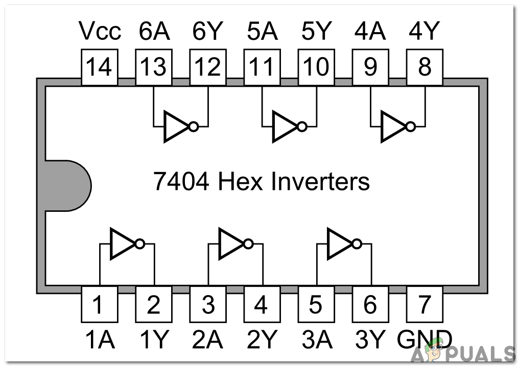
HEX Inverter IC-7404: This IC works strangely. It gives opposite/complemented output for a certain input or in layman terms we can say that if the Voltage at the input side is LOW, the voltage at the output side will be HIGH. This IC comprises six independent inverters and the operating voltage of this IC ranges within 4V-5V. The maximum voltage that this IC can bear is 5.5V. This inverter IC is the backbone of some electronic projects. Multiplexers and state machines may use this IC. The pin configuration of the inverter is shown in the diagram below:
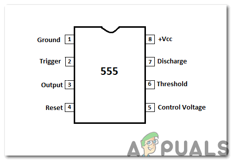
555 Timer IC: This IC has a variety of applications like providing time delays, as an oscillator, etc. There are three main configurations of the 555 timer IC. Astable multivibrator, monostable multivibrator, and bistable multivibrator. In this project, we will use it as an Astable multivibrator. In this mode, the IC acts as an oscillator that generates a square pulse. The frequency of the circuit can be adjusted by tuning the circuit. i.e. by varying the values of capacitors and resistors that are used in the circuit. The IC will generate a frequency when a high square pulse is applied to the RESET pin.
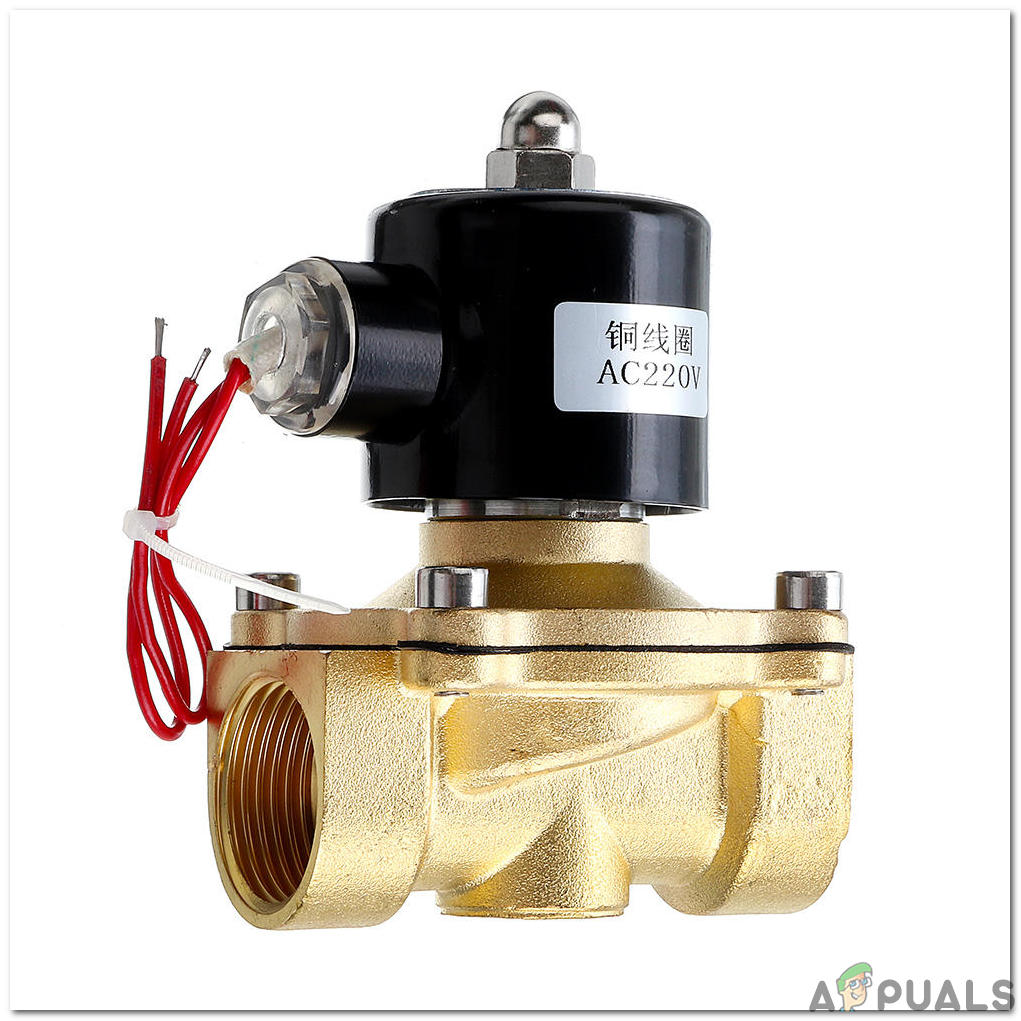
Electric Solenoid Valve: The electric valve is used to mix the flow of the gas or water in a pipe. It operates according to the electric circuit to which it is attached. This valve has two ports named as inlet and outlet and two positions open and closed.
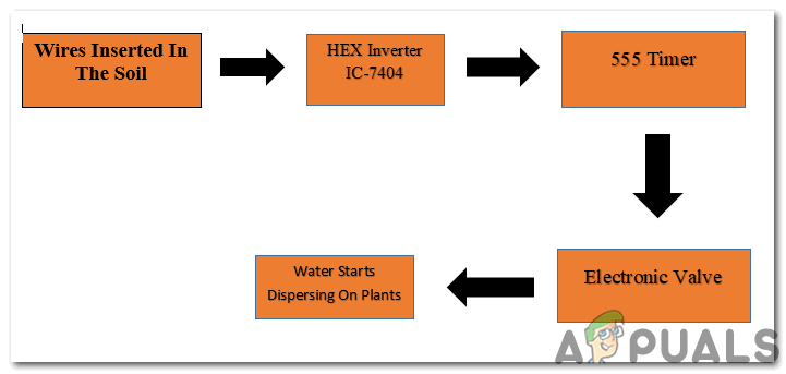
Step 4: Block Diagram
The block diagram needs to be examined before understanding the working principle:
Step 5: Understanding The Working Principle
The circuit is easy to understand. Our main concern is the soil of the plants because when the soil is dry it has high resistance and when it is wet it has low resistance. We will insert two conducting wires in the soil which will be responsible for activating the circuit. These wires will conduct when the soil is wet and they will not conduct when the soil is dry. The conductivity will be detected by the HEX inverter which will show the state as high when the input is low and vice-versa. When the state of the HEX inverter is high the 555 timer isic connected at the left in the circuit will be triggered and the 555 timer IC connected to the output of the first ic in the circuit will also be triggered. The positive terminal of the valve is connected to the output pin of the 555 timer ic and when that ic has triggered the circuit is activated and the electric valve is switched ON. As a result, the water starts to flow through the pipe in the soil. When the soil is watered the resistance starts to decrease and the probes that are responsible for conductance will make the output of the HEX inverter low due to which the state of 555 timer changes from HIGH to LOW, hence the conductivity is finished and the circuit is switched OFF.
Step 6: Working Of The Circuit
The wires that are inserted into the soil will only conduct when the soil is dry and they will stop conducting when the soil becomes wet. The power source of the circuit is the 9V battery. At the point when the soil is dry, it will be responsible for huge voltage drop because of the high resistance. This is detected by 7404 hex inverter and makes the first NE555 clock trigger which is working as a monostable multivibrator with the assistance of an electrical signal. There are two 555 timer IC’s installed in the circuit. The output of one IC is the input of the other IC hence when the first one that is located at the left is triggered the second one will also be triggered and the relay that is connected to the second IC will be responsible for turning ON the 6V relay. The relay is connected to the electric valve through an SK100 transistor. As soon as the relay is turned ON the water starts to flow through the pipe and as water continues to move inside the soil it’s resistance is decreased and then the inverter will stop triggering the 555 timer IC resulting in circuit cut-off.
Step 7: Simulating the circuit
Before making the circuit it is better to simulate and examine all the readings on a software. The software we are going to use is the Proteus Design Suite. Proteus is a software on which electronic circuits are simulated:
- After you download and install the Proteus software, open it. Open a new schematic by clicking the ISIS icon on the menu.
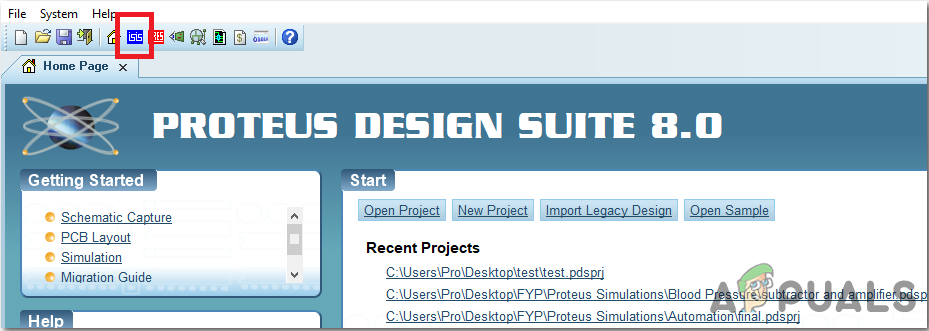
ISIS - When the new schematic appears, click on the P icon on the side menu. This will open a box in which you can select all the components that will be used.
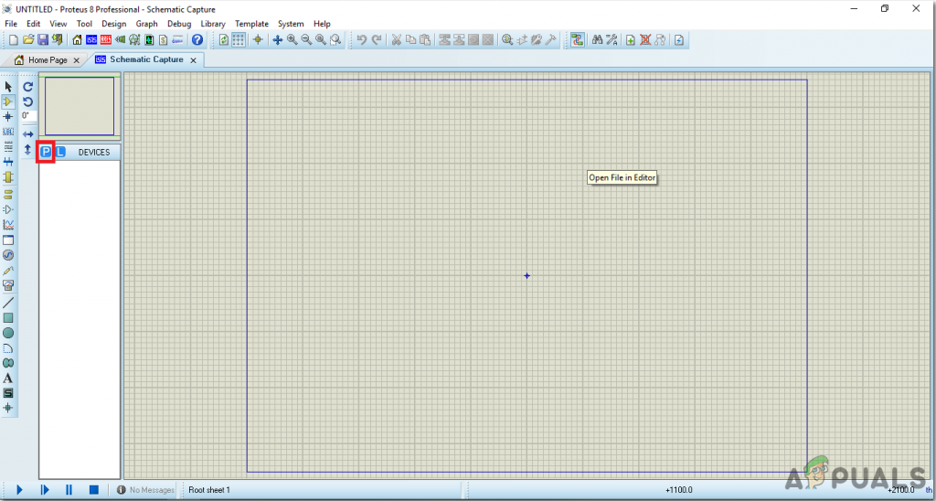
New Schematic - Now type the name of the components that will be used to make the circuit. The component will appear in a list on the right side.
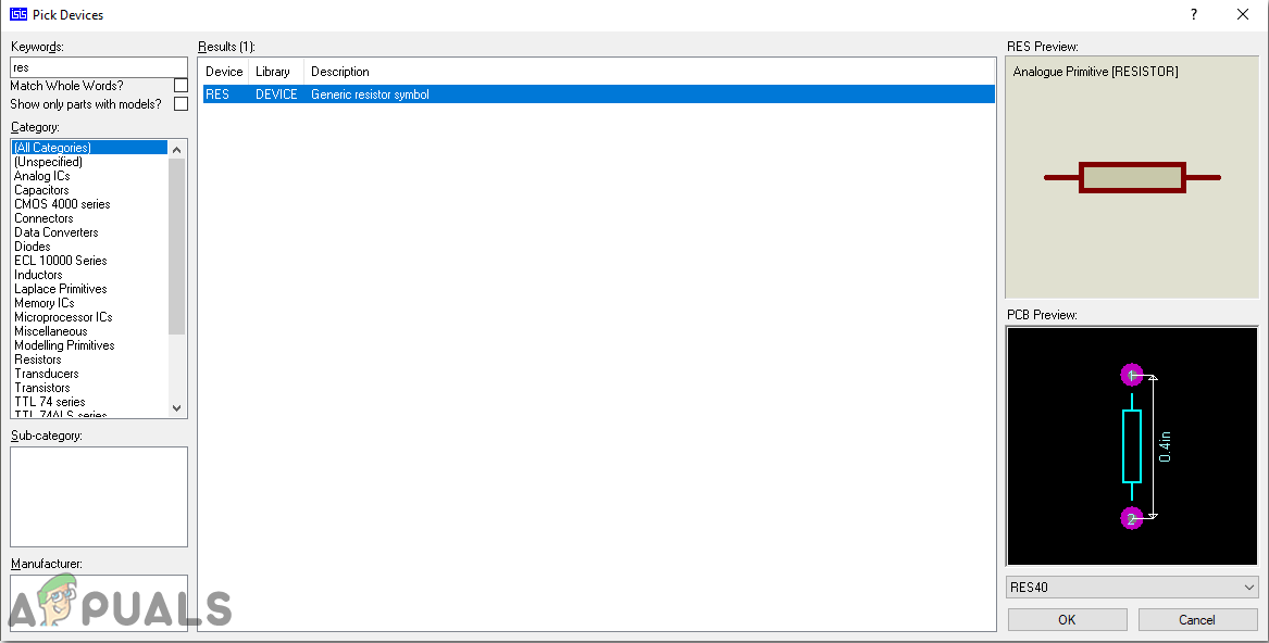
Selecting Components - In the same way, as above, search all the components. They will appear in the Devices List.
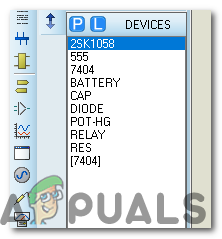
Component List
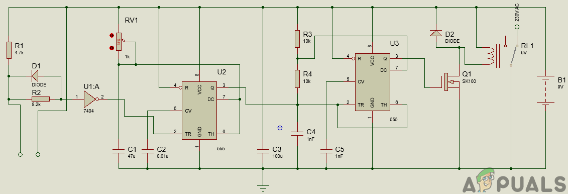
Step 8: Circuit Diagram
After assembling the components and wiring them the circuit diagram is shown as under:
Step 9: Making a PCB Layout
As we are going to make the hardware circuit on a PCB, We need to make a PCB layout for this circuit first.
- To make the PCB layout on Proteus, we first need to assign the PCB packages to every component on the schematic. to assign packages, right mouse clicks on the component you want to assign the package and select Packaging Tool.
- Click on the ARIES option on the top menu to open a PCB schematic.
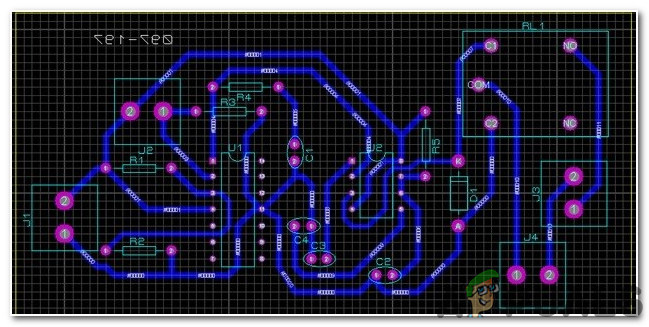
ARIES Design - From the Components List, Place all the components on the screen in a design you want your circuit to look like.
- Click on the track mode and connect all the pins that the software is telling you to connect by pointing an arrow.
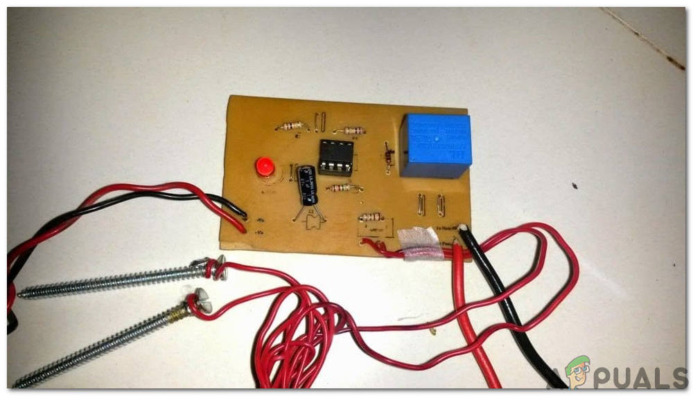
Step 10: Assembling The Hardware
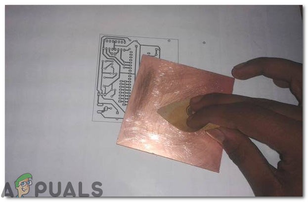
As we have now simulated the circuit on software and it is working perfectly fine. Now let us move ahead and place the components on PCB. A PCB is a printed circuit board. It is a board fully coated with copper on one side and fully insulating from the other side. Making the circuit on the PCB is comparatively a lengthy process. After the circuit is simulated on the software, and its PCB layout is made, the circuit layout is printed on a butter paper. Before placing the butter paper on the PCB board use the PCB scrapper to rub the board so that the copper layer on board is diminished from top of the board.
Then the butter paper is placed on the PCB board and ironed until the circuit is printed on the board (It takes approximately five minutes).

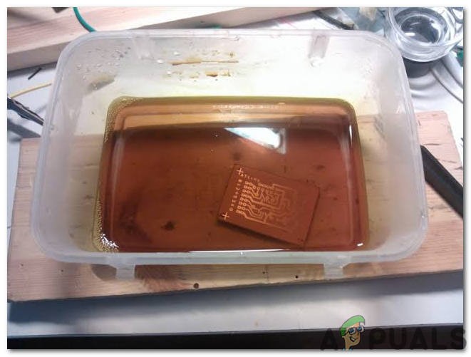
Now, when the circuit is printed on the board, it is dipped into the FeCl3 solution of hot water to remove extra copper from the board, only the copper under the printed circuit will be left behind.
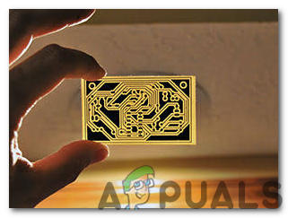
After that rub the PCB board with the scrapper so the wiring will be prominent. Now drill the holes in the respective places and place the components on the circuit board.
Solder the components on the board. Finally, check the continuity of the circuit and if discontinuity occurs at any place de-solder the components and connect them again. Apply hot glue gun on the circuit terminals so the battery may not be detached if any pressure is applied.
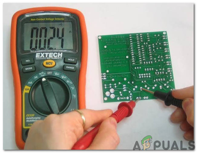
Step 11: Testing The Circuit
Now, our hardware is fully ready. Install the hardware at a suitable place in the garden and if the place is open insulate the circuit so that is doesn’t blow off due to rain etc. If the plants are dry the circuit will automatically turn ON and start watering the plants. That’s it! Now, you don’t need to manually water the plants every morning, whenever the plants are dry they will be watered automatically.
Applications
- It can be installed in gardens for domestic use.
- It can be used commercially too. E.g. In parks where there are ample plants.
- It can be installed in plant nurseries.


what is the use of potentiometer in the above circuit?