How To Make Arduino Based Traffic Light Controller?
Traffic Lights are signaling devices that are used to control the flow of traffic on the intersections of a road, pedestrian crossings, and other locations. It is a combination of three colors of light that are Red, Yellow and Green. The red light tells the people to stop, yellow tells to get ready or start the engine if it is turned off and the green light indicated that you are clear to go ahead.
In this project, we are going to make a 4-way traffic signal system using a microcontroller. We will burn a C Code on the Arduino Uno board to tell it how to turn the LEDs on and off so that the perfect timing of switching can be achieved in the signaling process. 4 combinations of 4 LEDs will be used and placed on the breadboard for the testing purpose.
How To Make 4-Way Traffic Signal Using Seeeduino v4.2?
Traffic signals are the most important thing that is installed on the roads to keep a smooth and steady flow of traffic and it minimizes the chance of accidents. We can make this project on a small breadboard. Let us gather some information about this project and start working.
Step 1: Collecting The Components
The best approach to start any project is to make a list of complete components at the start and going through a brief study of each component. This helps us in avoiding the inconveniences in the middle of the project. A complete list of all the components used in this project is given below.
- No products found.
- No products found.
- No products found.
- No products found.
- No products found.
Step 2: Studying The Components
Now as we know the abstract of our project and we also have a complete list of all the components, let us move a step ahead and go through a brief study of the components we are going to use.
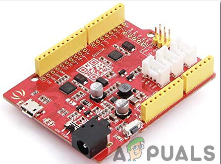
Seeeduino v4.2 is one of the best Arduino compatible boards in the world which is based on microcontroller Atmega 328 MCU. because it is easy to use, more stable and it looks better than many other boards. It is based on the Arduino bootloader. it has an ATMEGA16U2 as a UART-to-USB converter because oof which it can be used as an FTDI chip. it is connected to the computer by using a micro USB cable which is generally called an android cable. A DC jack can also be used to power the board. the input power must be from 7V to 15V.
A Breadboard is a solderless device. It is used to make and test temporary prototype electronic circuits and designs. Most of the electronic components are simply connected to a breadboard just by inserting their pins in the breadboard. A strip of metal is laid down the holes of the breadboard and the holes are connected in a specific way. The connections of the holes are shown in the diagram below:

Step 3: Working Principle
Let us go through a brief introduction to the working principle of the 4-way Traffic Signal project. As this is a 4-way, we will need twelve LEDs and four combinations of three LEDs. The code is written so that if one combination is showing a green light, all the other combinations will show red light. If a signal is changing from green to yellow or red to yellow, another combination of the LEDs will also show a transaction from red to yellow or yellow to red respectively.
This all will be done with a time delay between the transition of the signals. For example, an LED will remain green for almost fifteen seconds, an LED will remain yellow for almost two seconds. The duration of the Red LED depends upon the duration of the green LED. It means that if an LED is green for fifteen seconds, all the other red LEDs will remain on for fifteen seconds.
Step 4: Making The Circuit
Now as we know the main working of the components, let us move ahead and start assembling the components to make the circuit. Go through the following steps to connect all the components correctly in the breadboard.
- First of all, take all the LEDs and connect them in the breadboard in the right order as red, yellow and green.
- Make a common connection of the grounds of al the LEDs. It is better to connect a 220-ohm resistor to the positive terminal of the LED.
- Now Connect the connecting wires accordingly.
- Now connect the LEDs to the Arduino as shown in the circuit diagram below. LED-1, LED-2 up to LED-12 will be connected to pin1, pin2 up to pin12 of the Arduino Uno board.
- Upload the code in the Arduino Uno and power it by using a Laptop or the AC to DC adapter.
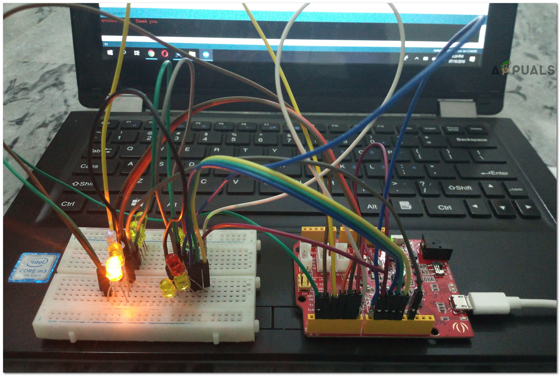
- The circuit will look like the image shown below:
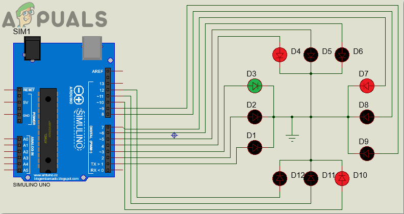
Circuit Diagram
Step 5: Getting Started With Arduino
If you are not familiar with Arduino IDE before, don’t worry because below, you can see clear steps of burning code on the microcontroller board using Arduino IDE. You can download the latest version of Arduino IDE from here and follow the steps mentioned below:
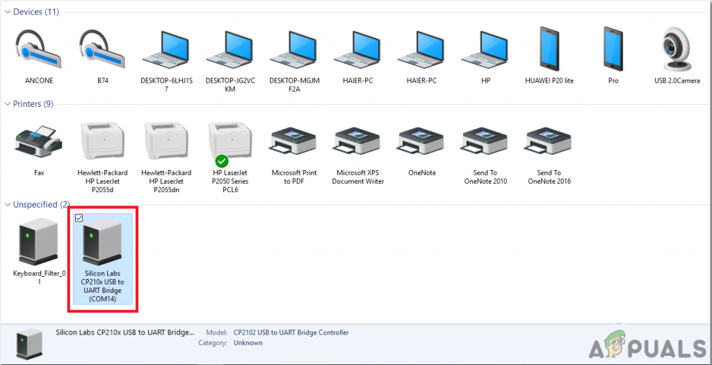
1). When the Arduino board is connected to your PC, open “Control panel” and click on “Hardware and Sound”. Then click on “Devices and Printers”. Find the name of the port to which your Arduino board is connected. In my case it is “COM14” but it may be different on your PC.
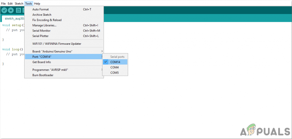
2). Now open the Arduino IDE. From Tools, set the Arduino board to Arduino / Genuino UNO.

3). From the same Tool menu, set the port number that you saw in the control panel.
4). Download the code attached below and copy it to your IDE. To upload the code, click on the upload button.

You can download the code by clicking here.
Step 6: Code
The code is well commented and self-explanatory but still, some part of code is briefly explained below.
1. At the start, all the pins are named, which will be connected to Arduino later.
int led1 = 1; // red light 1
int led2 = 2; // yellow light 1
int led3 = 3; // green light 1
int led4 = 4; // red light 2
int led5 = 5; // yellow light 2
int led6 = 6; // green light 2
int led7 = 7; // red light 3
int led8 = 8; // yellow light 3
int led9 = 9; // green light 3
int led10 = 10; // red light 4
int led11 = 11; // yellow light 4
int led12 = 12; // green light 4
2. void setup() is a function in which we declare all the pins of the Arduino board to be used as INPUT or OUTPUT. Baud Rate is also set in this function. Baud Rate is the communication speed in bits per second by which the microcontroller board communicates with the external devices. This function only runs once when the enable button of the microcontroller board is pressed.
void setup()
{
Serial.begin(9600;)   // Baud Rate is set to 9600
pinMode(led1,OUTPUT); // All the pins connected to LEDs are set as OUTPUT
pinMode(led2,OUTPUT);
pinMode(led3,OUTPUT);
pinMode(led4,OUTPUT);
pinMode(led5,OUTPUT);
pinMode(led6,OUTPUT);
pinMode(led7,OUTPUT);
pinMode(led8,OUTPUT);
pinMode(led9,OUTPUT);
pinMode(led10,OUTPUT);
pinMode(led11,OUTPUT);
pinMode(led12,OUTPUT);
}
3. void loop is a function which runs repeatedly in a loop. In this function, we will code the whole procedure by which the microcontroller will control the external LEDs. A small chunk of code is given below. Here the green light of the first side is on and all other sides have their red light on. These lights will remain in this state for 15 seconds. After 15 seconds, the yellow light of the first and second side will turn on the other two sides will have their red light remained on. After a delay of two seconds, the first side will have its red light on and the second side will have its green light on. This will happen until all the four sides have their green lights switched on, on their turn and then the loop will repeat itself.
digitalWrite(led1,LOW);  //Red light of first side is off
digitalWrite(led2,LOW);  // yellow light f first side is off
digitalWrite(led3,HIGH); // Green Light of First side is on
digitalWrite(led4,HIGH); // Red light of seconf side is on
digitalWrite(led5,LOW);  //yellow light of second side is off
digitalWrite(led6,LOW);  // green light of second side is off
digitalWrite(led7,HIGH); // Red light of third side is on
digitalWrite(led8,LOW);  // yellow light of third side is off
digitalWrite(led9,LOW);  // green light of third side is off
digitalWrite(led10,HIGH); // red light of fourth side is on
digitalWrite(led11,LOW);  // yellow light of fourth side is off
digitalWrite(led12,LOW);  // green light of fourth side is off
// because of a delay of 15 seconds the green light of first side
//and the red lights of other three sides will remain switched on for 15 seconds
delay(15000);

digitalWrite(led1,LOW);  // red  light of first side is off
digitalWrite(led2,HIGH); // Yellow light of first side is on
digitalWrite(led3,LOW);  // green light of first side is off
digitalWrite(led4,LOW);  // red light of second side is off
digitalWrite(led5,HIGH); // Yellow light of second side is on
digitalWrite(led6,LOW);  // green light of second side is off
digitalWrite(led7,HIGH); // Red light of third side is on
digitalWrite(led8,LOW);  // yellow light of third side is off
digitalWrite(led9,LOW);  // green light of third side is off
digitalWrite(led10,HIGH); // red light of fourth side is on
digitalWrite(led11,LOW);  // yellow light of fourth side is off
digitalWrite(led12,LOW);  // green light of fourth side is off
// because of a delay of 2 seconds, yellow light of the first and seond side will remain
//switched on
delay(2000);
So, this was the whole procedure to make a 4-way traffic signal. Now, you can enjoy making it for your learning or a school project.


