How To Make An Electric Mosquito Repellent?
Nowadays mosquitoes are becoming a very major headache because they have increased in number not only in the rural but also in urban areas. The most renown disease known as Dengue Virus is diagnosed in a patient after the mosquito bite and it is becoming a cause of deaths of people these days. These mosquitoes mainly attack edibles and human beings. There are many mosquitoes repellents available in the market. These repellents include coils, mats, cream, and liquid vaporizers. These all have their applications in many places. Many of these mosquitoes repellents have different effects on the human body. These effects can be in the form of allergic reactions, skin irritation, breathing problems, etc. To avoid all these problems, the best solution is to make an electrical circuit using some simple components that are easily available in the market.
Some electric mosquitoes repellent circuits are available in the market but we can easily make one at home that will be equally efficient but very low in cost. So, in this project, we are going to design a circuit that will be used to scare the mosquitoes away just by producing an ultrasound signal. We will use a 555 Timer IC to produce these signals.
How to make a circuit that Repels Mosquitos?
As we now know the main abstract of the out project let us move one step ahead and gather some more information to start working on this project. The first step is to make a list of the components and study them.
Step 1: Gathering The Components
The best approach to start any project is to make a list of components and going through a brief study of these components because no one will want to stick in the middle of a project just because of a missing component. A list of components that we are going to use in this project is given below:
- NE555 timer IC
- 9V Battery
- No products found.
- Piezo Buzzer
- Electrolyte capacitor of 0.01uF
- Ceramic capacitor of 0.01uF
- No products found.
- No products found.
- Connecting wires
Step 2: Principle behind the Project
The range of frequencies that is audible to a human ear ranges from 20Hz – 20kHz. Any range off a frequency that is above this range or below this range will be inaudible to a human ear. These ranges of frequencies are known as ultrasonic sound. Human and animals have a different range of frequencies that is audible to them. Many animals like cats, dogs, and other insects can hear the sound that is inaudible to the human ear i.e. ultrasonic sound. This ability to hear the ultrasound is also present in mosquitoes.
Stress is produced on the antenna of the mosquito by ultrasound waves. Generally, after breeding, female mosquitos avoid the ultrasound waves that are mostly produced by the male mosquitoes. This reason can be used to repel them away just by generating the ultrasound wave of the same frequency.
So, the main aim is to generate an ultrasound wave whose frequency ranges from 20kHz – 38kHz. Ultrasound waves of these frequencies will help to scare the mosquitoes away.
Step 3: Circuit Design
So, the heart of the circuit is an Astable Multivibrator circuit that will work as an oscillator. To make this oscillator circuit, a 555 Timer IC is used. This circuit will drive a piezo buzzer which will produce an ultrasound wave and send it in the surrounding.
To calculate the values of the components that will be suitable to design the circuit to produce a frequency that is required is given be
F = 1.44((Ra+Rb*2)*C)
Ra = 1.44(2D-1)/(F*C)
Rb=1.44(1-D)/(F*C)
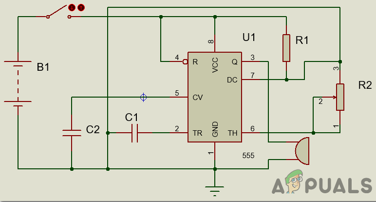
In the above formula, we will assume the value of the capacitor and find out the value of other components. other components include the resistors Ra, which is connected between pin7 of the timer IC and Vcc, and Rb, which is connected between pin7 and pin6 of the timer IC. D is the duty cycle. We will select the value of the capacitor as 0.01uF. The value of frequency and the duty cycle that is required is 38kHz and 60% respectively. Substitute these values in the above formulas and find the values of the resistors.
Pin1 of the 555 Timer IC is the ground Pin. Pin2 of the timer IC is the trigger pin. the second pin of the Timer IC is known as the Trigger Pin. If this pin is directly connected to pin6, it will work in Astable mode. When the voltage at this pin drops below one-third of the total input, it will get triggered. Pin3 of the timer IC is the pin where the output is sent. Pin4 of the 555 Timer Ic is used for the reset purpose. It is initially connected to the positive terminal of the battery. Pin5 of the timer IC is the control pin and it does not have much use. In most of the cases, it is connected to the ground through a ceramic capacitor. Pin6 of the timer IC is named as the threshold pin. pin2 and pin6 are shorted and are connected to pin7 to make it operate in Astable mode. When the voltage of this pin gets greater than two-third of the mains voltage supply, the Timer IC will come back to its stable state. Pin7 of the Timer IC is used for the discharge purpose. The capacitor is given the discharge path through this pin. Pin8 of the timer Ic is directly connected to the ground.
Step 4: Understanding the Circuit
An electronic circuit that produces a pulsed output is known as a multivibrator circuit. the nature of the pulse depends on the nature off the output. If a vibrator has only one stable state, it is known as a monostable vibrator circuit. If a vibrator has two stable states, it is known as a bistable vibrator circuit. If a vibrator has no stable state, it is known as an Astable vibrator circuit. An Astable vibrator is used as an oscillator and a bistable vibrator is used as a Schmitt Trigger.
An astable multivibrator produces oscillation without external triggering. In our project, we are using the astable mode of the multivibrator IC.
Step 5: Working of the Project
The working principle of the project is quite simple. As soon as we power ON the circuit by closing the switch the 555 timer IC is turned ON. As the capacitor (C1) is initially uncharged hence it’s voltage is zero and the trigger pin of the 555 timers is also zero. The resistors Ra and Rb are responsible for charging the capacitor (C1). The voltage at the trigger pin is less than the capacitor voltage hence it causes a change in timer output. When the supply is turned ON the capacitor (C1) starts discharging through R(B). This process continues until the voltage comes back to the original state. This results in an output signal that is 38kHz. The resultant signal is sent to the piezo buzzer which will be used to generate the ultrasound wave that will scare away the mosquitoes. The output frequency can also be varied by using the potentiometer present in the circuit.
Step 6: Assembling The Components
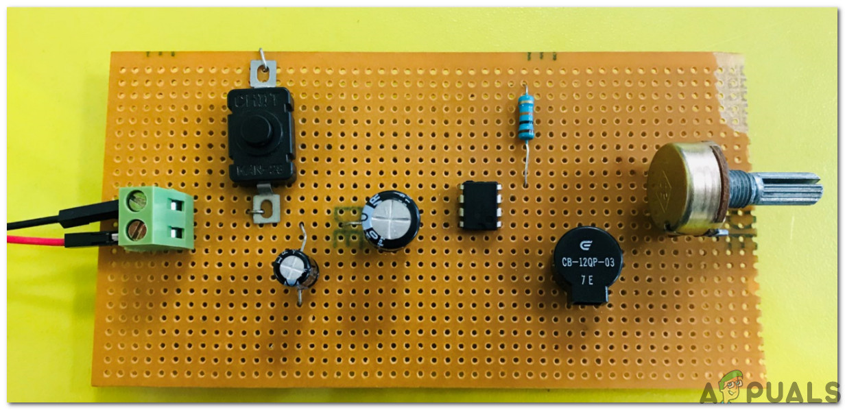
Now, as we know the main connections and also the complete circuit of our project, let us move ahead and start making the hardware of our project. One thing must be kept in mind that the circuit must be compact and the components must be placed so close.
- Take a Veroboard and rub its side with the copper coating with a scraper paper.
- Now Place the components carefully and close enough so that the size of the circuit does not become very big
- Carefully make the connections using solder iron. If any mistake is made while making the connections, try to desolder the connection and solder the connection again properly, but in the end, the connection must be tight.
- Once all the connections are made, carry out a continuity test. In electronics, the continuity test is the checking of an electric circuit to check whether current flow in the desired path (that it is in certainty a total circuit). A continuity test is performed by setting a little voltage (wired in arrangement with a LED or commotion creating part, for example, a piezoelectric speaker) over the picked way.
- If the continuity test passes, it means that the circuit is adequately made as desired. It is now ready to be tested.
- Connect the battery to the circuit.
The circuit will look like the image below:
Applications
There are some applications of this circuit. Two of them are listed below:
- If this circuit is modified, by generating a signal of a specific signal, it can be used to repel other insects too.
- This circuit can be used as a simple buzzer alarm circuit.
Limitations
Although this circuit is simple and works good but still it has some limitations. Some of its limitations are given below:
- This circuit will work efficiently if the population of mosquitos is not very large.
- A lot of frequency settings are required to tune it to give the maximum output.
- Ultrasound signals, when leaving the source, take a path that is 45 degrees to the source. So, if there is any obstacle in the way of these signals, they will divert their path.


