How To Make An AutoLacing Shoe Using Arduino?
In the modern era, scientists and engineers are trying to make everything automated. It means that everything will work on its own without any human effort. A very common problem was identified in the society that some people have trouble tying their shoelaces by themselves. These people include disabled, people with back pain, children and blind people to some extent. So, a solution is to be made so that these people don’t see this as a problem.

In this project, we are going to make an Automatic Lacing show which will automatically tie its laces without any human effort. It will do it with the help of microcontroller board, a motor shield sensor, and a servo motor, as soon as one places the foot inside the shoe.
How To AutoLace Your Show Using Arduino?
Now, as we know the abstract of the project, let us start collecting more information and go through the procedure of how to make this AutoLace shoe using Arduino.
Step 1: Collecting The Components
The best approach to start any project is to make a list of components and going through a brief study of these components because no one will want to stick in the middle of a project just because of a missing component. A list of components that we are going to use in this project is given below:
- Arduino Uno
- Motor Shield
- No products found.
- Force
- No products found.
- No products found.
- Shoe
- Metal Strip
- Plastic Zip Ties
- 1/8
- No products found.
- Battery
Step 2: Studying The Components
Now as we know the abstract of our project and we also have a complete list of all the components, let us move a step ahead and go through a brief study of the components we are going to use.
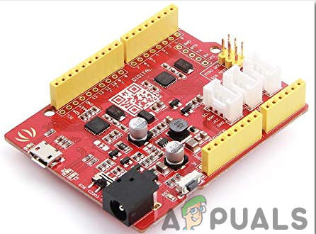
Seeeduino v4.2 is one of the best Arduino compatible boards in the world which is based on microcontroller Atmega 328 MCU. because it is easy to use, more stable and it looks better than many other boards. It is based on the Arduino bootloader. it has an ATMEGA16U2 as a UART-to-USB converter because oof which it can be used as an FTDI chip. it is connected to the computer by using a micro USB cable which is generally called an android cable. A DC jack can also be used to power the board. the input power must be from 7V to 15V.
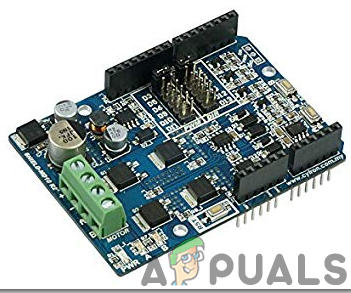
Arduino Motor Shield enables you to effortlessly control motor direction and speed utilizing an Arduino. By enabling you to just address Arduino pins, it makes it easy to drive any motor into your undertaking. It additionally enables you to have the option to control a motor with a different power supply of up to 12v. Best of all, the shield is very easy to find. For all of these reasons, the Arduino Motor Shield if a cool little to have in your arsenal for rapid prototyping, and general experimenting.
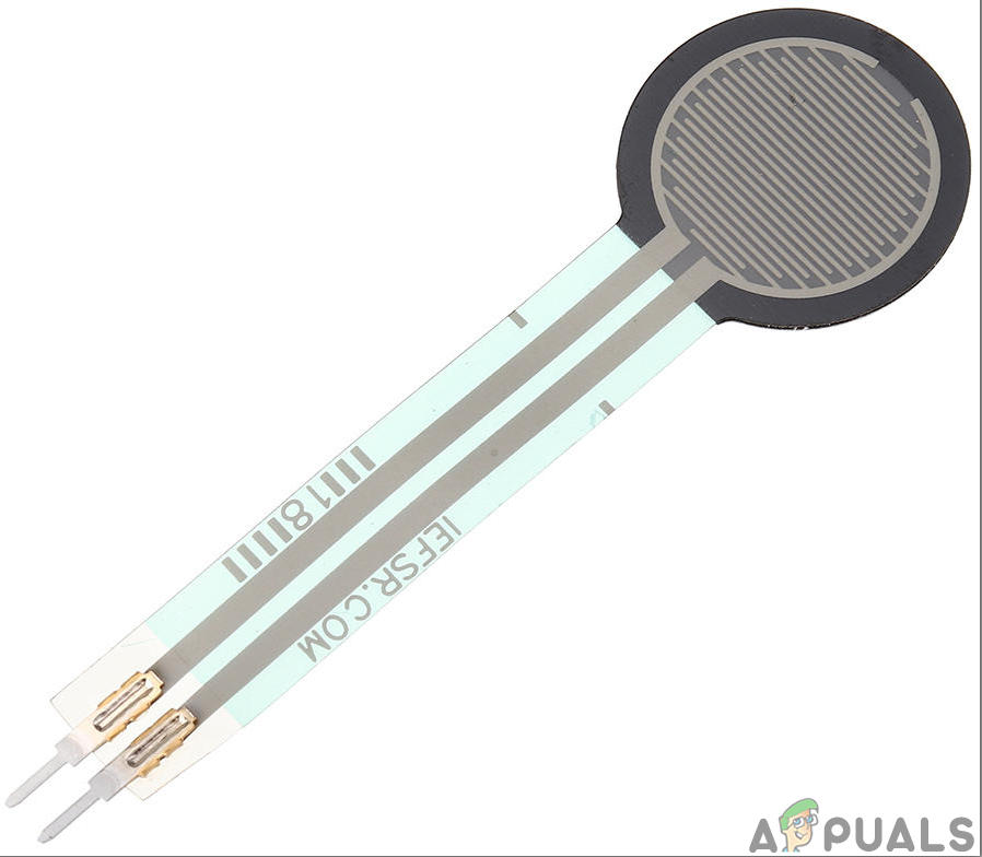
Force Sensor Resistors (FSRs) are very simple and easy to use pressure sensors. The obstruction of an FSR relies upon the weight that is applied to the detecting territory. The more weight you apply, the lower the opposition. The obstruction range is quite huge: > 10 MΩ (no weight) to ~ 200 Ω (max weight). Most FSRs can detect power in the scope of 100 g to 10 kg. An FSR comprises of two layers and a spacer adhesive. The conducting layers are isolated by a slim air gap when no weight is applied. One of the films contains two traces running from the tail to the detecting region (the round part). These traces are woven together, however not contacting. The other film is covered with a leading ink. When you push on the sensor, the ink shorts the two traces together with an opposition that relies upon the weight.
A Servo Motor is a rotatory or a linear actuator which can be controlled and moved in exact increment. These motors are different from DC motors. These motors allow the precise control of angular or rotatory motion. This motor is coupled to a sensor which is sending feedback about its motion.

Step 3: Working Principle
The working principle of this project is very simple. A force sensor will be used to detect if the foot is placed in the show or not. If it detects the foot, it will send a signal to the Arduino board which will move a servo motor with the help of an Arduino Motor Shield. This servo motor will move in such a way that it will pull all the laces at once. Hence automatically tying all the laces of the shoe.
Step 4: Assembling The Components
Now as we know the main idea and the working principle behind this project, let us move a step ahead and start assembling everything to make a show that will automatically lase itself. To make a final product, go through the steps given below:
- First of all, trim a small metal plate so that it is fixed on the back of the show. Use a synthetic so that it fixes permanently and does not loosen up. Make sure you leave a gap between the metal plate and the show because we will pass some cable ties fro that gap.
- Now take two servo motors and attach them to the metal plate with hot glue. Now to make this them fixed permanently, use zip ties around them so that these servo motors do not move later. After the servo motors are in pace, cut the extra cable that is left.
- Now mount a battery case beneath the motors so that it’s power switch is outwards.
- Now attach the Arduino board on the motors. Before, connecting the motor shield with the Arduino, some things need to be added to the circuit.
- Take an LED and solder a resistor to its positive leg and solder a short length of wire to the negative leg and the other leg of the resistor. Then connect this assembly to the Arduino and push it to one of the unused shoelace sockets.
- Now take a Force Sensor and place it in your shoes where your heel will rest. it is not recommended to solder the pins of the force sensor because the heat of the soldering iron can melt away the plastic of the sensor. So its better if u glue it or duct tape it.
- Finally use a zip tie to tie all the laces to the servo motor, so that when the motor rotates, it pulls all the laces at once.
Make sure the positive wire of the LED is connected to pin2 of Arduino. The Vcc and ground pin of the Force Sensor will be connected to the 5V and ground of the Arduino and the IN pin of the force sensor will be connected to the A0 pin of the Arduino board. Finally, plug the Servo Motor pins to the motor shield carefully so that you don’t make a wrong connection.
Step 5: Getting Started With Arduino
If you are not familiar with Arduino IDE before, don’t worry because below, you can see clear steps of burning code on the microcontroller board using Arduino IDE. You can download the latest version of Arduino IDE from here and follow the steps mentioned below:
- When the Arduino board is connected to your PC, open “Control panel” and click on “Hardware and Sound”. Then click on “Devices and Printers”. Find the name of the port to which your Arduino board is connected. In my case it is “COM14” but it may be different on your PC.

Finding Port - We will have to include a library to use Servo Motor. The library is attached below in the download link along with the code. Go to Sketch > Include Library > Add .ZIP Library.

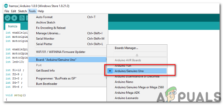
Include Library - Now open the Arduino IDE. From Tools, set the Arduino board to Arduino / Genuino UNO.
Setting Board - From the same Tool menu, set the port number that you saw in the control panel.

Setting Port - Download the code attached below and copy it to your IDE. To upload the code, click on the upload button.

Upload
You can download the code by clicking here.
Step 6: Code
The code is pretty well commented and self-explanatory. But still, the code is briefly explained below.
1. At the start, a special library is included so that the servo motor can be integrated with the microcontroller board and programmed through it. Two objects are created to be used with the servo motor. some pins or Arduino are initialized that will be connected to the motor driver and some variables are also declared that will save some temporary values that will be later used in the main program.
#include <Servo.h>      // include library to interface servo motor with miccrocontroller board

Servo myservo;          // creates servo objec 1
Servo myservo2;         // create servo object 2

int forcePin = 0;       // analog pin 0 connected to force sensor
int ledPin = 2;         // digital pin 2 connected to LED
int switchPin = 19;     // sets unlock switch to analog pin 5
int valF;               // value of force sensor
int valS;               // value of switch
int thresHold = 500;    // defines force sensor pressure threshold
int servoUnlock = 0;    // sets main servo to neutral unlaced position (0 degrees)
int servoLock = 180;    // sets main servo to laced position (180 degrees)
int servoUnlock2 = 180; // sets auxillary servo to neutral unlaced position (0 degrees)
int servoLock2 = 0;     // sets auxillary servo to laced position (180 degrees)
2. void setup() is a function that runs only one time in the start when the microcontroller is powered ono or the enable button is pressed. In this function, the pins of the Arduino are initialized to be used as INPUT or OUTPUT. Objects that were created for servo motor before, are being used to attach the servo motor to the specific pin of the Arduino board and the servo is being moved to the initial unlaced condition. Baud Rate is also set in this function. Baud Rate is the speed in bits per second by which the microcontroller communicates with the external devices attached.
void setup()
{
Serial.begin                  // setting the baud rate of the microcontroller
pinMode(ledPin, OUTPUT);      // digital pin 2 is output for LED
pinMode(switchPin, INPUT);    // analog pin 5 is input for switch
myservo.attach(9);            // attaches the servos to pins 9
myservo2.attach(10);          // attaches the servos to pins 10
myservo.write(servoUnlock);   // move servo 1 into unlaced positions
myservo2.write(servoUnlock2); // move servo 2 into unlaced positions
}
3. void loop() is a function that runs repeatedly in a loop. First, an analog value s being read by the force sensor. Then it waits for the value of the force sensor to pass a threshold value. It will wait for the foot to completely settle in its place and will set both the servos to a lock position. If the switches are pressed, the servo will be set to unlock and will wait until the LED will bling seven times.
void loop()
{
 valF = analogRead(forcePin);            // read value of force sensor
 valS = digitalRead(switchPin);          // read value of switch

 if (valF>=thresHold) {                  // waits for force sensor to equal or pass pressure threshold
  delay(1000);                           // waits for foot to settle into place in shoe
  myservo2.write(servoLock2);            // sets auxillary servo to locked position
  delay(1000);                           // waits one second
  myservo.write(servoLock);              // sets main servo to locked position
  delay(1000);                           // waits one second
  digitalWrite(ledPin, HIGH);            // turns on LED untill servo unlocked.
 }

 if (valS == HIGH) {                     // waits for switch to be pressed, and then:
  myservo2.write(servoUnlock2);          // unlocks auxillary servo
  delay(1000);                           // waits two seconds
  myservo.write(servoUnlock);            // unlocks main servo
  delay(500);                            // wait, then blink LED 7 times
  digitalWrite(ledPin, LOW);
  delay(200);
  digitalWrite(ledPin, HIGH);
  delay(200);
  digitalWrite(ledPin, LOW);
  delay(200);
  digitalWrite(ledPin, HIGH);
  delay(200);
  digitalWrite(ledPin, LOW);
  delay(200);
  digitalWrite(ledPin, HIGH);
  delay(200);
  digitalWrite(ledPin, LOW);
  delay(200);
  digitalWrite(ledPin, HIGH);
  delay(200);
  digitalWrite(ledPin, LOW);
  delay(200);
  digitalWrite(ledPin, HIGH);
  delay(200);
   digitalWrite(ledPin, LOW);
  delay(200);
  digitalWrite(ledPin, HIGH);
  delay(200);
  digitalWrite(ledPin, LOW);
  delay(200);
  digitalWrite(ledPin, HIGH);
  delay(200);
  digitalWrite(ledPin, LOW); // turns LED off
  delay(1000);
 }
}
So this was the whole procedure to make a show which automatically ties its laces by itself with the help of a servo motor, microcontroller, and a motor shield. Now as you know this whole procedure, enjoy making your AutoLacing Show at your home.


