How To Make A Variable Power Supply?
Every electrical component is the globe directly or indirectly needs the power to operate. To supply required power, a device known as a power supply is used. A power supply is an electrical unit whose job is to provide power to electrical loads. The function of a power supply is to take input voltage from the source and supply the required voltage to power the loads connected to the output terminal. A general-purpose power supply unit is used is homes, offices, colleges, etc. It takes 220V input from the mains supply and has various output terminals to power-up loads that do not require high voltage. The output terminal is mostly of fixed 5V, 12V, and variable 0-30V.
How to Make a Small Power Supply unit?
The power supply is the most essential part of any project to run the whole hardware. Let’s get started and collect some more data to start the project. We will make a Printed Circuit Board (PCB) for this project.
Step 1: Collecting the Components
The best approach to start any project is to make a complete list of components. This is not only an intelligent way to start a project but it also saves us from many inconveniences in the middle of the project. A list of components, which are very easily available in the market, is given below:
Step 2: Studying the Components
As now, we have a complete list of all the components, let us move a step ahead and go through a brief study of all the components.
A Transformer is a passive electrical device that is used for increasing or decreasing the alternating voltage in electrical power applications. There are two types of transformers, a Step-down Transformer, and a Step-Up Transformer. Here we are using a Step-Down Transformer. this type of transformer is the most common to be used in household appliances because it reduces the high voltage from the main to 12V. First, the circuit is made and then it runs to take all the measurements. The basic construction of a transformer consists of a coil and two windings, a primary winding, and a secondary winding. In a step-down transformer, the primary windings are greater than the secondary windings which help in reducing the primary voltage to the secondary voltage.
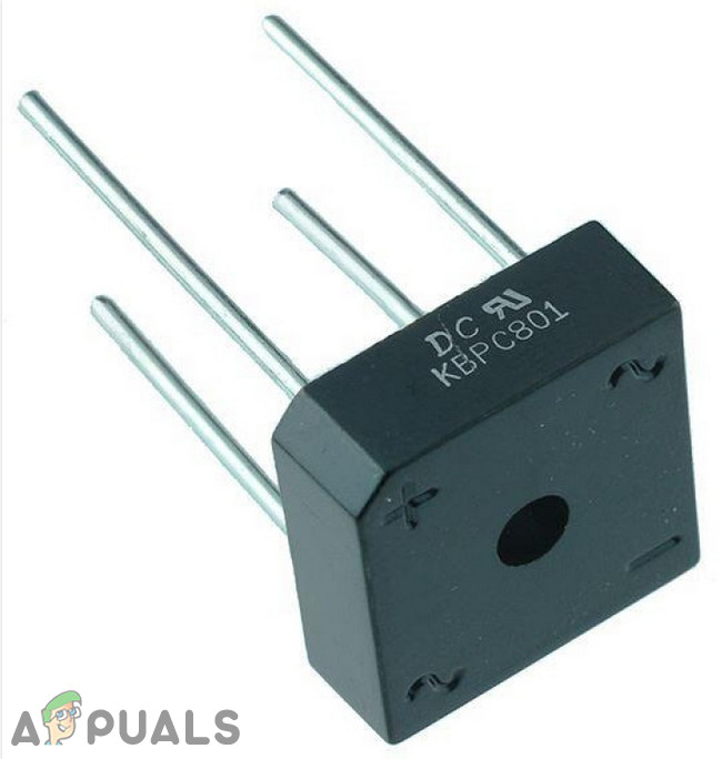
A diode is an electrical component whose job is to conduct unidirectional current. We have made a rectifier bridge using four diodes in our circuit. A bridge rectifier is a full-wave rectifier that turns Alternating current (AC) into Direct Current (DC). When AC voltage passes through the bridge rectifier, During the first half cycle, two of its diodes become forward biased and two of them become reversed biased, resulting in the conduction of one cycle. during the second half cycle, the diodes which were reversed biased before, now become forward biased and the other two become reversed biased, hence making the other half cycle appear in the positive. The final result is a DC wave.
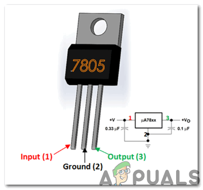
7805 Voltage regulator: Voltage regulators have significant importance in electrical circuits. Even if there is fluctuation in input voltage, this voltage regulator provides a constant output voltage. We can find the application of the 7805 IC in most of the projects. The name 7805 signifies two meanings, “78” means that it is a positive voltage regulator and “05” means that it provides 5V as output. So our voltage regulator will provide a +5V output voltage. This IC can handle current around 1.5A. A Heat sink is recommended for projects that consume more current. For example, if the input voltage is 12V and you are consuming 1A, then (12-5) * 1 = 7W. This 7 Watts will be dissipated as heat.
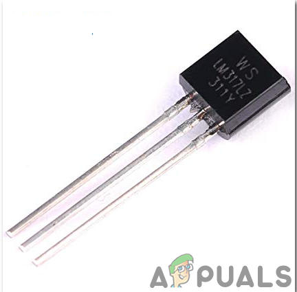
LM317 is also a voltage regulator but it is not fixed. It is an adjustable linear voltage regulator. It can handle up to 1.5A current and can regulate voltage from 1.25V to approximately 37 volts. It needs an external resistance to vary the voltage. It has many applications, for example, it is used in motor drivers, power banks, chargers, ethernet switches, etc.
Step 3: Simulating the circuit
Before making the circuit it is better to simulate and examine all the readings on a software. The software we are going to use is the Proteus Design Suite. Proteus is a software on which electronic circuits are simulated. First, the circuit is made and then it runs to take all the measurements. The basic construction of a transformer consists of a coil and two windings, a primary winding, and a secondary winding. In a step-down transformer, the primary windings are greater than the secondary windings which help in reducing the primary voltage to the secondary voltage.
To download the software, click here.
- After you download and install the Proteus software, open it. Open a new schematic by clicking the ISIS icon on the menu.
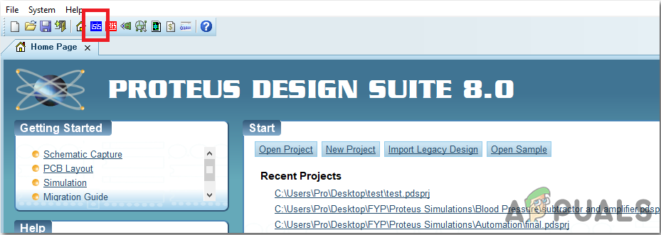
ISIS - When the new schematic appears, click on the P icon on the side menu. This will open a box in which you can select all the components that will be used.
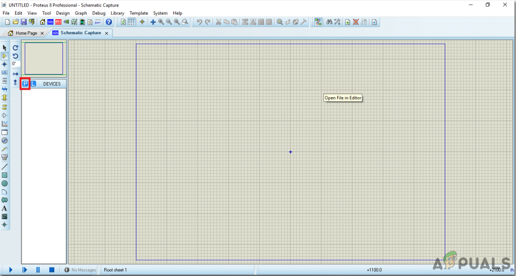
New Schematic - Now type the name of the components that will be used to make the circuit. The component will appear in a list on the right side.
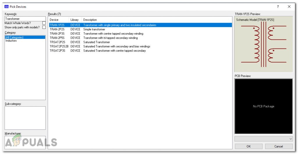
Searching components - In the same way, as above, search all the components. They will appear in the Devices List.
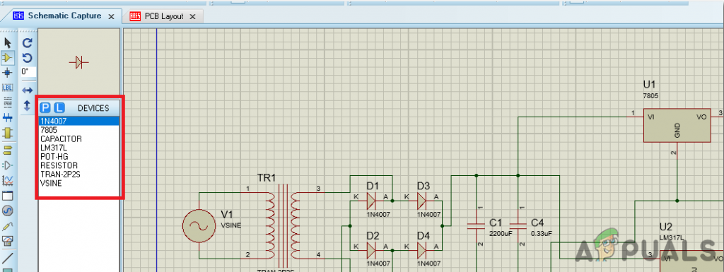
components List - Now as we have made the whole circuit on software. Let us simulate it check if the output we are getting is desired or not. We want to get fixed 5V on one terminal and variable 0 to 12V on the second terminal. For this, we will connect a voltmeter and take all the readings. First, we will set the Voltage of the main AC voltage source to 220V and its frequency to 50Hz. To change the output of the second terminal, we will slide the knob of pot-hg which is our variable resister.
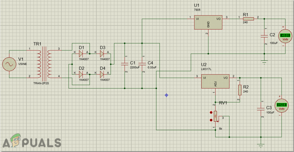
Taking Readings
Step 4: Making a PCB Layout
As we are going to make the hardware circuit on a PCB, We need to make a PCB layout for this circuit first.
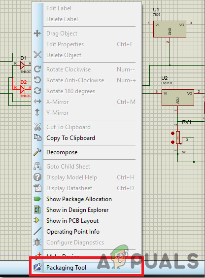
- To make the PCB layout on Proteus, we first need to assign the PCB packages to every component on the schematic. to assign packages, right mouse clicks on the component you want to assign the package and select Packaging Tool.
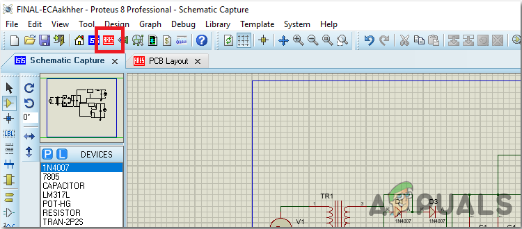
Assign Packages - Click on the ARIES option on the top menu to open a PCB schematic.
Aries - From the Components List, Place all the components on the screen in a design you want your circuit to look like.
- Click on the track mode and connect all the pins that the software is telling you to connect by pointing an arrow.
- When the whole layout is made, it will look like this.
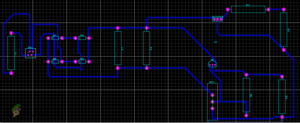
PCB Layout
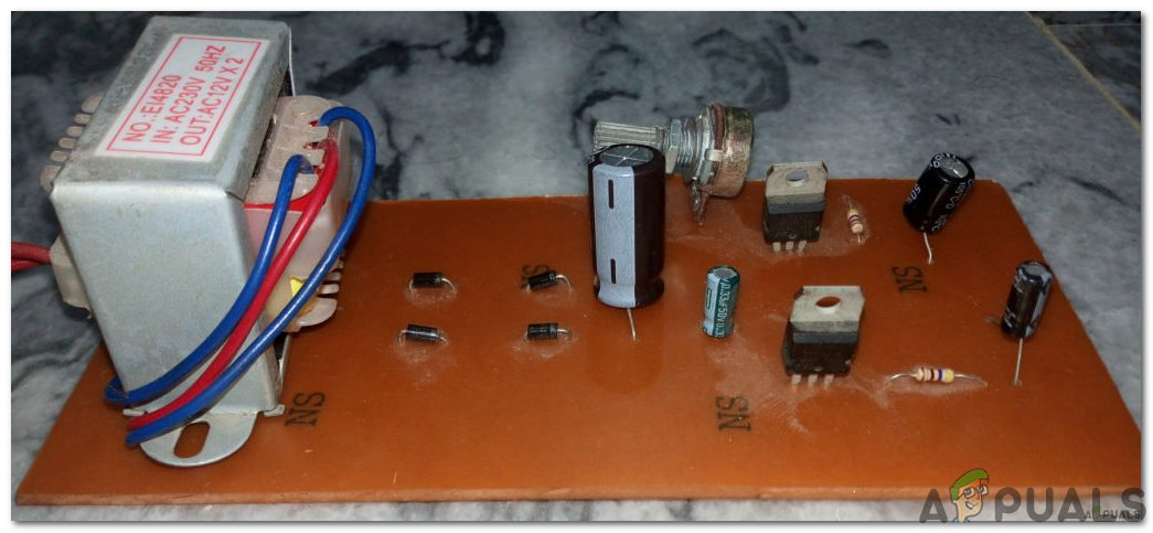
Step 5: Making the Hardware
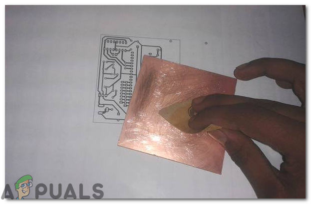
As we have now simulated the circuit on software and it is working perfectly fine. Now let us move ahead and place the components on PCB. A PCB is a printed circuit board. It is a board fully coated with copper on one side and fully insulating from the other side. Making the circuit on the PCB is comparatively a lengthy process. After the circuit is simulated on the software, and its PCB layout is made, the circuit layout is printed on a butter paper. Before placing the butter paper on the PCB board use the PCB scrapper to rub the board so that the copper layer on board is diminished from top of the board.
Then the butter paper is placed on the PCB board and ironed until the circuit is printed on the board (It takes approximately five minutes).

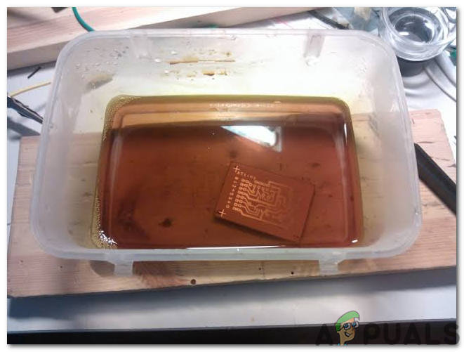
Now, when the circuit is printed on the board, it is dipped into the FeCl3 solution of hot water to remove extra copper from the board, only the copper under the printed circuit will be left behind.
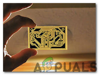
After that rub the PCB board with the scrapper so the wiring will be prominent. Now drill the holes in the respective places and place the components on the circuit board.
Solder the components on the board. Finally, check the continuity of the circuit and if discontinuity occurs at any place de-solder the components and connect them again.
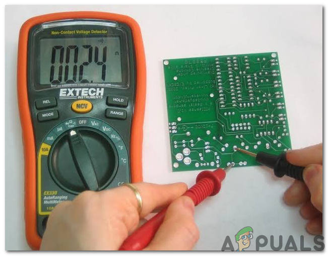
Step 6: Testing the Circuit
Now the hardware is fully ready. Let us run a test and measure the voltages. connect the primary terminals of the transformer to the man source to power it up. Connect an led with a 1k-ohm resistor to the 5V output terminal of the power supply and a small DC motor to the variable output terminal. Switch on the mains supply and you will see that the led will glow. To test the variable voltage, change the knob of the variable resistor. With the change in the resistance of the variable resistor, the speed of the motor should change. If this all happens, it means that we have made a good power supply which can be used for different purposes, for example, charging of batteries, running small school projects, power up toys, etc.


