How To Make A PiezoElectric Battery Charging Shoe?
The device failure due to the lack of energy is a common problem nowadays. Many times important phone calls are left unattended and we aren’t able to reply to an important conversation which is going on between our colleagues and us, just because of the drainage of our mobile phone battery. Almost every person who possesses a smartphone wishes that he/she should have more battery life. So, keeping this problem under consideration we will design a mobile charging technique using our shoes. This project will not only solve the battery drainage problem but it will also promote health by creating a shoe insole that converts the physical energy created by walking into electricity, which is then stored in a portable battery pack. Along with charging our electronic gadget, we will also be able to renew some of our physical energy too.
How To Assemble Piezoelectric Elements With Other Components?
As we have understood the basic aim of our project, let’s move a step ahead and look out for the required components and then integrate them to design a final prototype.
Step 1: Components Used
- No products found.
- PiezoElectric Elements (x14)
- No products found.
- Hot Glue Gun
- Soldering Iron Kit
- No products found.
- 1N4001 - 1N4007 Diodes (x4)
- Dremel Tool
- Velcro Strips
- Digital Multi Meter
- Architectural Scale Ruler
Step 2: Understanding the Basic Principle Of The Project
Before assembling the components we need to understand the working mechanism of the project. In every project of electronics, the power supply is the backbone. The main power source that makes this project possible is called a piezoelectric transducer/piezoelectric element. They are comprised of components like crystals and ceramics that have the special ability to convert physical energy into AC electricity. We can make the best use of this property of these elements by putting them underneath our feet in such a way that every time we take a step our weight is used to push the piezoelectric elements, which in turn converts our physical energy into electrical energy. Electrical energy is generated but there is a slight problem, Alternate Current (AC). We need Direct Current (DC) for our project. Hence, this problem will be solved by creating a Bridge Rectifier with diodes so that AC power can be converted into DC power.

Step 3: Measuring The Size Of Your Shoe
The first element that we need for designing a piezoelectric generator is the plastic base. Take out the base from the shoe and make appropriate measurements using the architectural scale ruler.
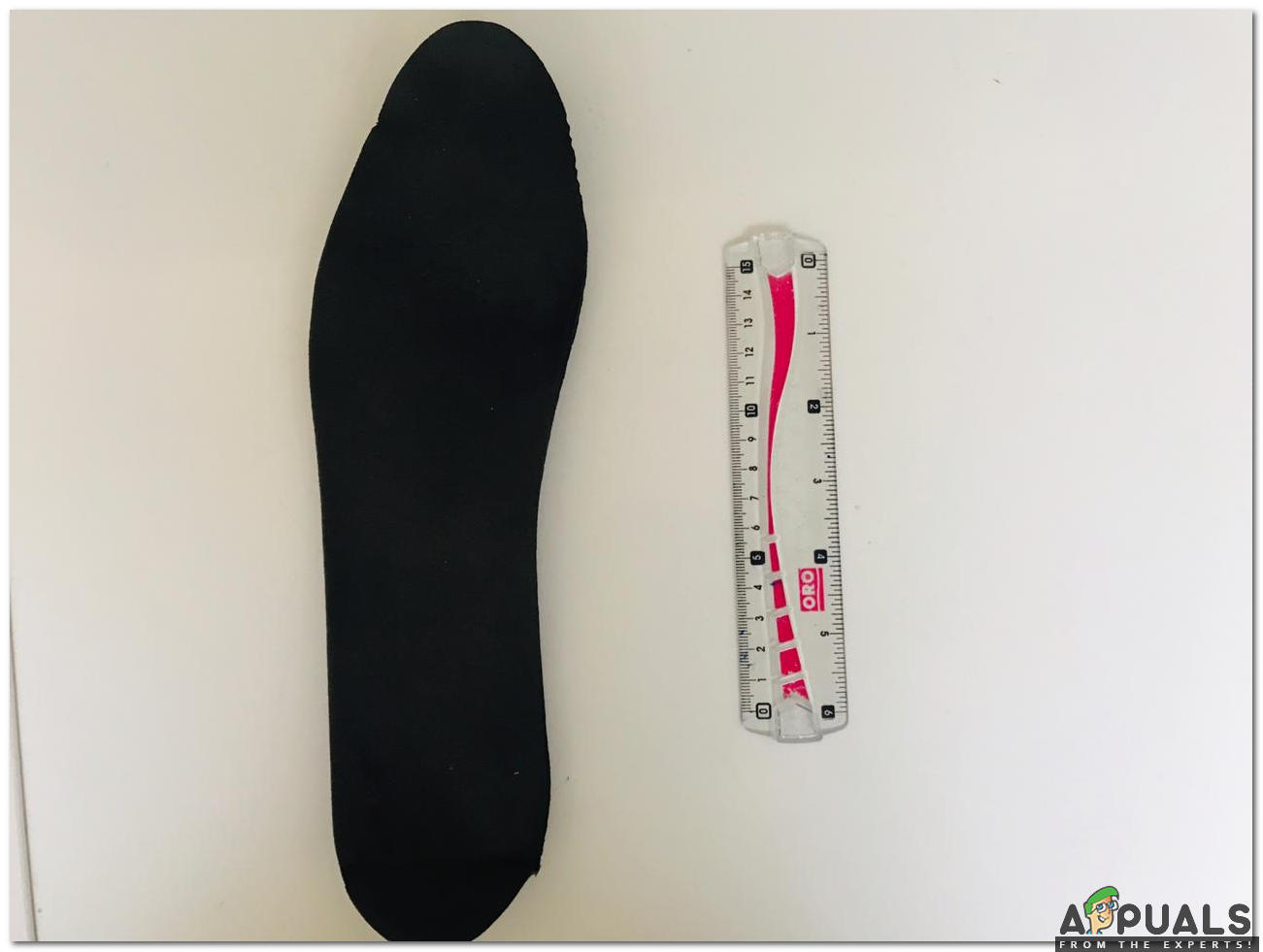
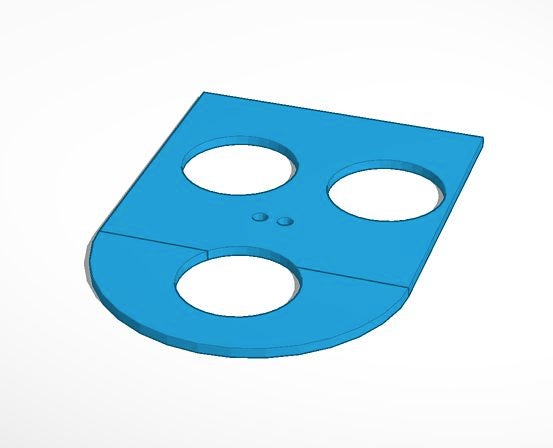
The piezo element holes are strategically placed so that they line up with the large indents on the shoe’s insole, which indicate the areas of most pressure.
Step 4: GLUING THE PIEZO ELEMENTS
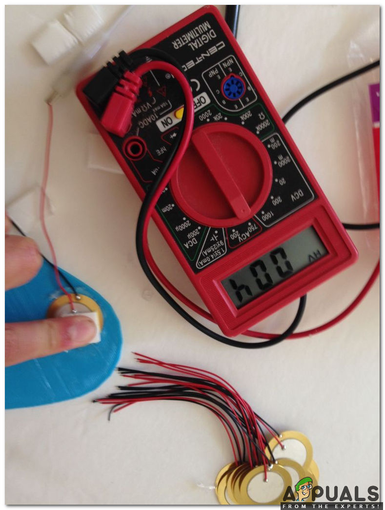
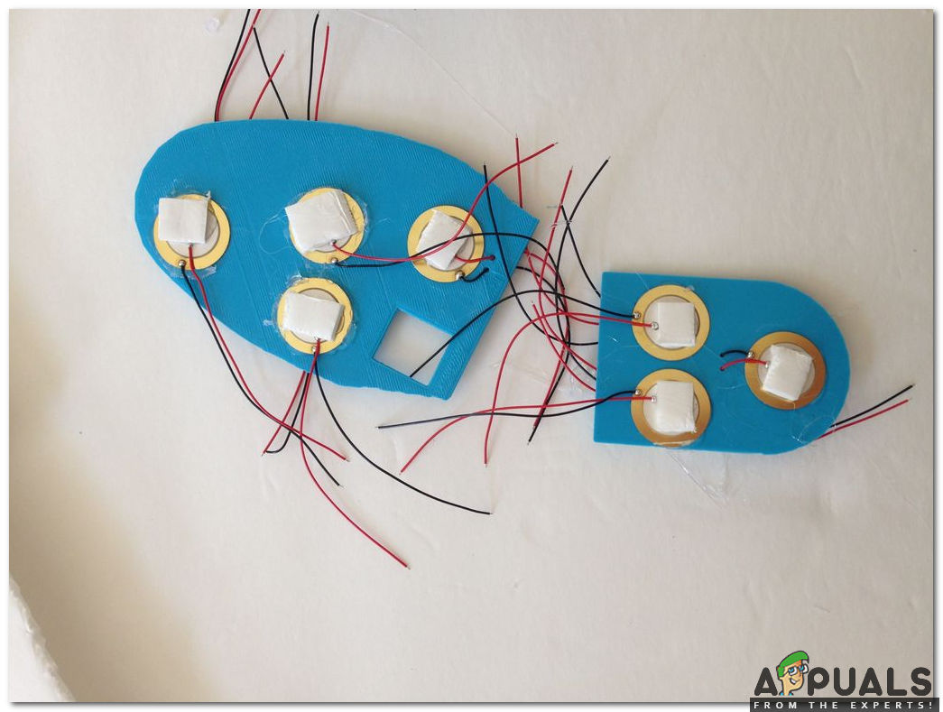
As we have finished creating the base for our piezoelectric generator, we will paste the piezo elements on base with the help of a hot glue gun. Apply the thin layer of glue around the edge of the hole in the plastic and then quickly press the piezoelectric components on it before it is cooled down. Don’t apply too much glue because in case we do so, we may restrict the foam pads from fully compressing. We will take care of one more thing that the glue doesn’t touch the Positive (RED) and Negative (BLACK) joints because that joints will be soldered later on. We will ensure that the piezo elements are glued on both sides of the plastic. Using a digital multimeter we will make sure that our piezo elements are working.
Now, as we have glued all of the piezoelectric elements in their appropriate spots, we will glue the foam pieces onto each piezo element as shown below:
Step 5: SOLDERING THE PIEZO ELEMENTS TOGETHER
The piezo elements generate ample voltage but they don’t generate considerable current. So, keeping this in view we will wire all the piezo elements in parallel (positives will be soldered with the positive ones and negatives will be soldered with the negative ones). As we have done this we will be able to generate a large number of amperes and our device will be charged faster. After soldering the joints apply the hot glue on the joints as it will prevent the joints from breaking off. We will connect the piezo elements from one side of the plastic to the other by threading the wires of one of the piezo elements through the holes so that they can be soldered in parallel to a piezo on the other side. As all of the piezo elements on the heel are wired in parallel, we will solder the last piezo in the chain to one of the piezo elements on the toe piece, and continue to solder the piezo elements in parallel until all 14 elements are connected.
Step 6: Building The Bridge Rectifier
Moving a step ahead, firstly, we will study the circuit diagram of a bridge rectifier, secondly, we will build a bridge rectifier using diodes and finally, we will wire the bridge rectifier.
- Studying The Circuit Diagram: When the voltage is applied to the diodes and they allow the current to pass- through they are said to be in forwarding Biased mode and when the voltage is applied and diodes don’t allow the current to pass-through then they are said to be in Reverse Biased mode. In the circuit diagram is shown below the diodes are connected in forwarding biased mode and they allow the current to pass through them. The positive side of the diode is that side which is painted grey and it will be shown in the next step.
Circuit Diagram - Building The Bridge Rectifier: We will connect diodes according to the forward-biased configuration so, that current can be passed through them. The beginners could follow the diagram shown below to create the bridge rectifier. The bridge rectifier is also known as the Full Wave Rectifier.
Bridge Rectifier - Wiring The Bridge Rectifier: Now, connect the piezoelectric components to the rectifier according to the diagram shown below. The current is AC so, the position of the wires are interchangeable, as long as they connect to the correct diodes in the diagram. Peel the USB cable that you bought with your battery pack and take out the internal wires. We are only interested in RED and BLACK wires. Now, twist the frayed wire strands of each wire and then solder them and also solder the wires to the rectifier. As we know that DC voltage has positive and negative terminals so, after soldering it is better to check polarity. To be on the safer side apply hot glue gun on the terminals.
USB Cable attached to the rectifier
Step 7: Installation And Finishing Touches
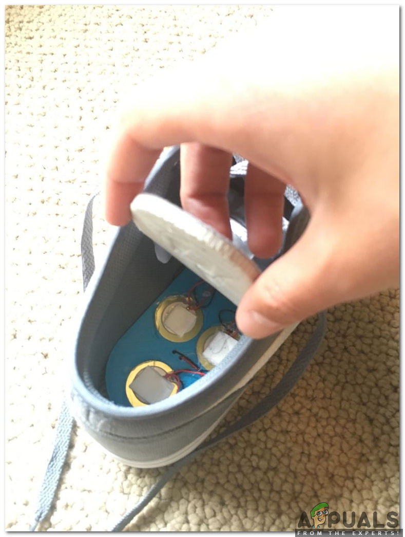
As we have assembled all of the components and our piezoelectric generator is ready, we will move towards the installation part. Adjust the plastic piezoelectric generator inside the shoe and then insert the original sole on top of it. In case somebody has an issue of adjusting the generator inside he/she can refer to the picture shown below:
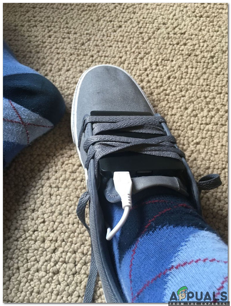
Take the USB cable wired previously and thread it between the tongue and the outside of your shoe. Now, the battery is left to be mounted and to do so, we will fix it between the tongue of the shoe and laces and then tight the shoe tightly. It is better to use Velcro to fasten the battery pack to prevent the battery from falling out while running. If anyone has a spare shoe then he/she can make a foam cutout from it’s sole and the shoe will rise a little bit.
Step 8: Testing
Now, as we have completed the installation part, we should test it, and see whether it’s working or not. To check how well they work we should EXERCISE daily. Play sports every day except for football because your phone can be damaged while hitting the ball from the foot. The battery will charge only whenever we take a step so, as many steps we take our phone is charged more rapidly.


thank you for detailed explanation!!