How To Make A Lead Acid Battery Charger?
Lead Acid Batteries were introduced many years ago but due to their better performance and low cost, they are still used by car industries mainly. They are famous for their high current providing capacity they are preferred over other conventional batteries that are available in the market. The battery should be properly charged and properly discharged for maximizing the battery timing and ensuring a longer life. In this project, I will make the lead-acid battery charging circuit using the electronic components that are readily available in the market.
How To Make a Battery Charger Circuit Using LM7815 IC?
The best approach to start any project is to make a list of components and going through a brief study of these components because no one will want to stick in the middle of a project just because of a missing component. The Printed Circuit Board is preferred for assembling the circuit on hardware because if we assemble the components on breadboard they may detach from it and the circuit will become short hence, PCB is preferred.
Step 1: Collecting The Components (Hardware)
- No products found.
- No products found.
- 1n4732 Diode (x1)
- 10k Ohm Resistor (x1)
- 50k Ohm Potentiometer (x1)
- 1.5k Ohm Resistor (x2)
- 1k Ohm Resistor (x2)
- No products found.
- 1.2k Ohm Resistor (x1)
- 1 Ohm Resistor (x1)
- 12V DC Relay
- Screw Driver
- Mini Heat Sink
- 9V DC Battery (x2)
- 9V Battery Clip (x2)
- LEDs (x4)
- No products found.
- FeCl3
- No products found.
- Printed Circuit Board
- Hot Glue Gun
- No products found.
Step 2: Components Needed (Software)
- Proteus 8 Professional (Can be downloaded from Here)
After downloading the Proteus 8 Professional, design the circuit on it. I have included software simulations here so that it may be convenient for beginners to design the circuit and make appropriate connections on the hardware.
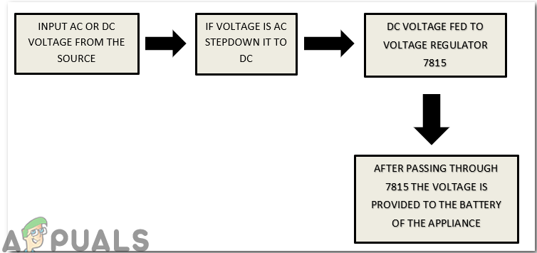
Step 3: Block Diagram
The block diagram is made for the convenience of the reader so that he/she could be able to understand the step by step working principle of the project quite easily.
Step 4: Understanding The Working Principle
In order to charge a battery the voltage that is at the input side would be stepped down first, then it will be rectified and then it will be filtered in order to maintain a constant DC supply. The voltage that will be at the output side of the circuit will then be fed into the battery that we want to charge. There are two options for the power source. One is AC and the other one is DC. It is the choice of the person who is designing the circuit. If he/she has a DC battery it could be used and it is recommended because the circuit becomes complex when we use transformers for converting AC into DC. If one doesn’t have a DC battery AC to DC adapter can be used.
Step 5: Analysing The Circuit
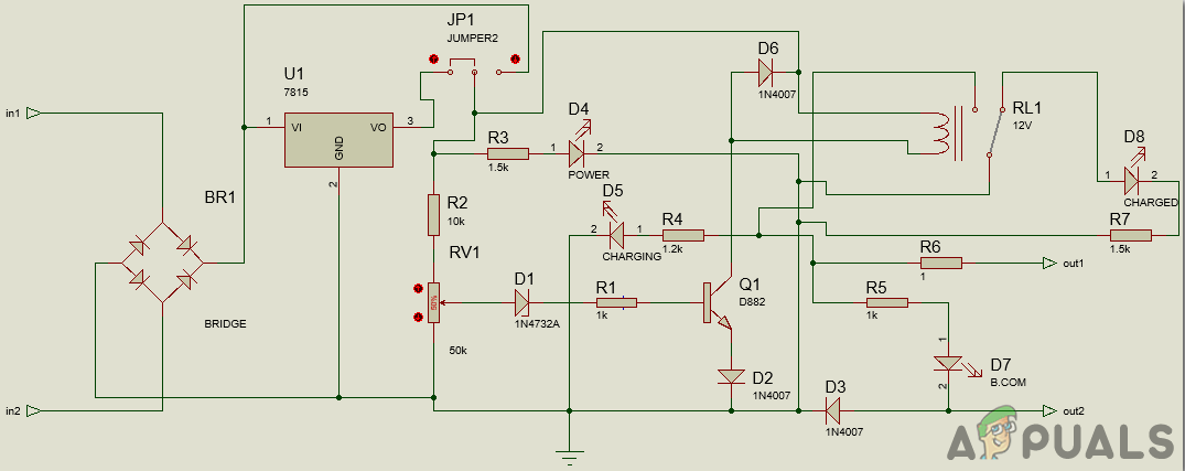
The major portion of the circuit consists of a Bridge Rectifier on the left. The 220V AC is applied at the input side and it is stepped down to the 18V DC. Instead of applying the AC voltage, a DC battery could also be used as a power source for operating the circuit. That input voltage whether it is AC or DC is applied to the LM7815 voltage regulator and then capacitors are connected to purify the voltage so that pure voltage can be applied further to the Relay. After passing through the capacitor voltage enters the Relay and appliance that is connected to the circuit starts charging through 1 Ohm resistor. At the point when the charging voltage of the battery arrives at the stumbling point, for example, 14.5V, the Zener diode starts conduction and gives enough base voltage to the transistor. Due to this conduction, the transistor goes in saturation region and it’s output becomes HIGH. Due to that high output, the relay becomes active and the appliance is disconnected from the supply.
Step 6: Simulating The Circuit
Before making the circuit it is better to simulate and examine all the readings on a software. The software we are going to use is the Proteus Design Suite. Proteus is a software on which electronic circuits are simulated.
- After you download and install the Proteus software, open it. Open a new schematic by clicking the ISIS icon on the menu.
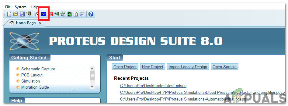
ISIS - When the new schematic appears, click on the P icon on the side menu. This will open a box in which you can select all the components that will be used.
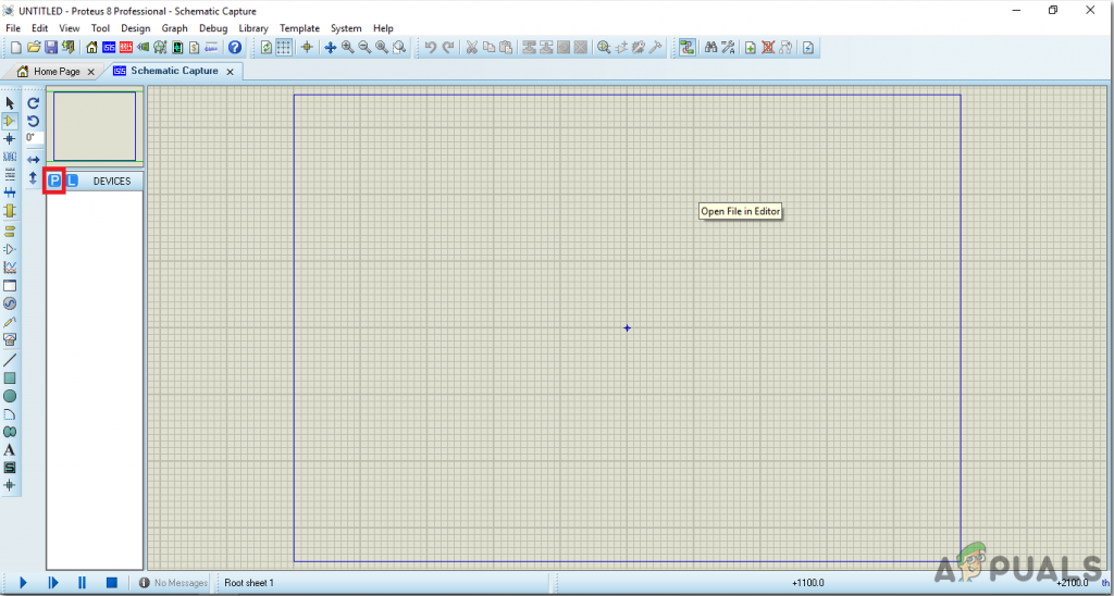
New Schematic - Now type the name of the components that will be used to make the circuit. The component will appear in a list on the right side.
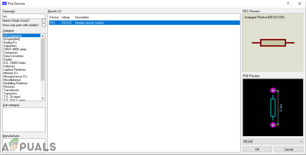
Selecting Components - In the same way, as above, search all the components. They will appear in the Devices List.
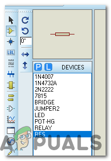
Component List
Step 7: Making a PCB Layout
As we are going to make the hardware circuit on a PCB, We need to make a PCB layout for this circuit first.
- To make the PCB layout on Proteus, we first need to assign the PCB packages to every component on the schematic. to assign packages, right mouse clicks on the component you want to assign the package and select Packaging Tool.
- Click on the ARIES option on the top menu to open a PCB schematic.
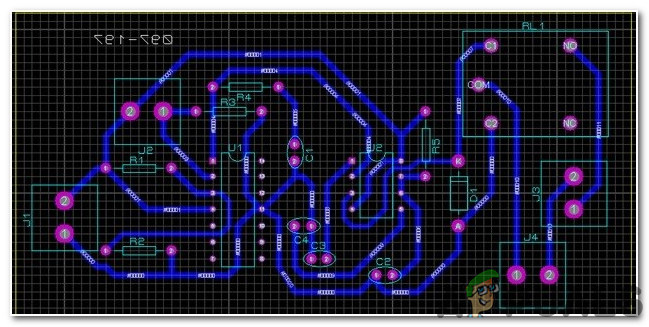
ARIES Design - From the Components List, Place all the components on the screen in a design you want your circuit to look like.
- Click on the track mode and connect all the pins that the software is telling you to connect by pointing an arrow.
Step 8: Circuit Diagram
After making the PCB layout the circuit diagram will look like this:
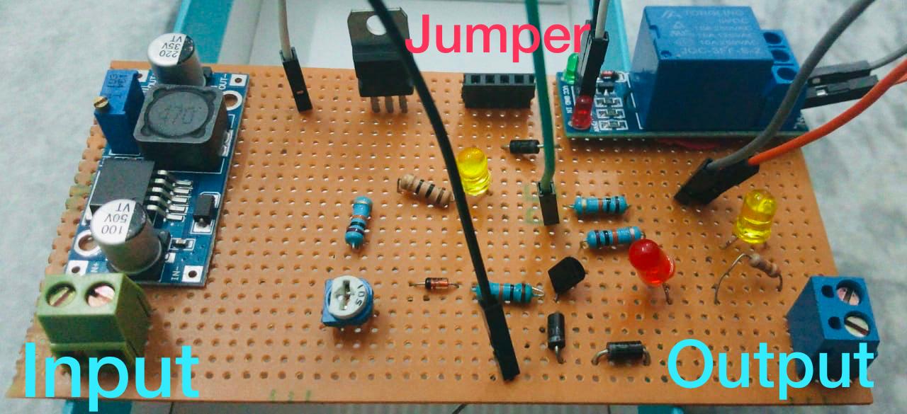
Step 9: Setting Up The Hardware
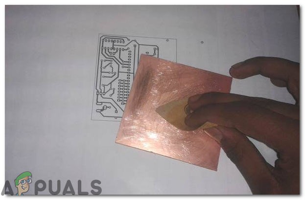
As we have now simulated the circuit on software and it is working perfectly fine. Now let us move ahead and place the components on PCB. After the circuit is simulated on the software, and its PCB layout is made, the circuit layout is printed on a butter paper. Before placing the butter paper on the PCB board use the PCB scrapper to rub the board so that the copper layer on board is diminished from top of the board.
Then the butter paper is placed on the PCB board and ironed until the circuit is printed on the board (It takes approximately five minutes).

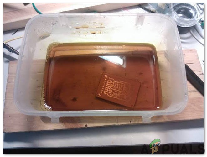
Now, when the circuit is printed on the board, it is dipped into the FeCl3 solution of hot water to remove extra copper from the board, only the copper under the printed circuit will be left behind.
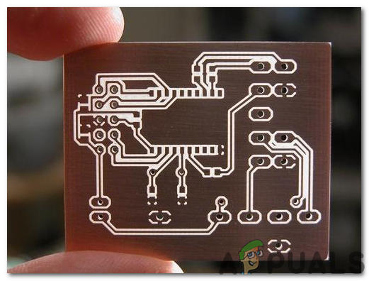
After that rub the PCB board with the scrapper so the wiring will be prominent. Now drill the holes in the respective places and place the components on the circuit board.
Solder the components on the board. Finally, check the continuity of the circuit and if discontinuity occurs at any place de-solder the components and connect them again. In electronics, the continuity test is the checking of an electric circuit to check whether current flow in the desired path (that it is in certainty a total circuit). A continuity test is performed by setting a little voltage (wired in arrangement with a LED or commotion creating part, for example, a piezoelectric speaker) over the picked way. If the continuity test passes, it means that the circuit is adequately made as desired. It is now ready to be tested. It is better to apply hot glue using a hot glue gun on the positive and negative terminals of battery so that the terminals of the battery may not be detached from the circuit.
Step 10: Testing The Circuit
After assembling the hardware components on the PCB board and checking the continuity we need to check whether our circuit is working properly or not we will test our circuit. The power source mentioned in this article is the 18V DC battery. In most cases, an 18V battery isn’t available and there is no need to panic. We can create an 18V battery by connecting two 9V DC batteries in Series. Connect the positive (Red) wire of the battery 1 to the negative (Black) wire of the battery 2 and similarly connect the negative wire of battery 2 to the positive wire of battery 1. For your ease the sample connections are shown below:
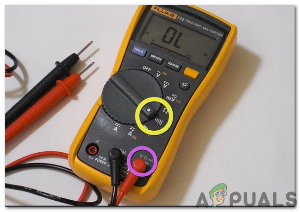
Before turning ON the circuit note down the voltage by using Digital Multimeter. Set the DMM to Volts and connect it to the positive and negative terminals of the lead-acid battery that needs to be charged. After noting down the voltage turn ON the circuit, wait for almost 30 minutes and then note down the voltage. You would see that the voltage would have increased and the lead-acid battery is in the charging state. We can test this circuit on a car battery because it is also a lead-acid battery.
Step 11: Calibrating The Circuit
The circuit needs to be calibrated for proper charging. Set the voltage to 15V in the bench power supply and connect it to CB+ and CB- point of the circuit. At first, set the jumper between positions 2 and 3 for calibration. After that pick up the screwdriver and rotate the potentiometer (50k Ohm) until the LED at the left side turns ON. Now, turn OFF the power supply and connect the jumper between point 1 and point 2. As we have tuned the circuit we are in a position to charge any lead-acid battery. The 15V that we have set during the calibration is the tripping/stumbling point of the circuit and battery will charge for around 80% of its capacity at this point. If we want to charge it for 100% the LM7815 needs to be removed and 18V is directly provided from the supply to the circuit and it isn’t recommended at all because it could damage the battery.


