How To Make A GSM Based Home Security System?
Street crimes are becoming very common nowadays. With the increase in these street crimes, the production of security systems is also increasing in the current century. Different types of modern security systems are available in the market that is very efficient and can alert the owner in seconds if an intruder tries to enter the area under surveillance. These alerts can be in the form of a siren, an alarm or a phone call. These security systems are very expensive and most of the people can not afford them if they want to install it on a small scale like homes.
So in this article, we have discussed a method to make a security system that will be as efficient as the system available in the market but will be very low in cost. This project can be made from the components that are easily available in the market. The heart of this project is Arduino Uno which is the microcontroller used in this project. The PIR sensor will sense any motion in the range of 6 meters and if the motion is detected, it will send a signal to the microcontroller. Arduino will then use a GSM module to first send an SMS to the owner and then make a call on the specified number.
How to Make A Security Alarm Using GSM Module?
Enough security from burglars, smoke, fire, etc. can be provided by using modern security systems. These security systems alert us as soon as they detect any unknown object moving into the area under surveillance. So the main aim of this project is to make a low-cost and efficient intruder alert system that will send an SMS to the owner and with a delay of two seconds, call him when it detects any intruder.
Step 1: Gathering The Components
Before starting any project, make sure you have all the components that you are going to use in the project. If you don’t have all of them, the best approach is to make a complete list of all the components and buy them from the market in the first place. This is an excellent technique if you want to save a lot of time and want to prevent yourself from getting stuck in the middle of the project. A complete list of all the components that we are going to use in this project is given below:
- Arduino Uno
- No products found.
- No products found.
- No products found.
- No products found.
Step 2: What is GSM?
The GSM module we are using here is SIM900A. It is a very reliable and ultra-compact module. It is a complete dual-band GSM/GPRS solution. It has a built-in RS232 interface. It works on a range of 900/1800 MHz frequency. The RS232 interface helps this module to be connected to a PC or any other microcontroller serially. After it is connected to a microcontroller using a serial cable, it can send SMS, make voice calls or access the internet.
Step 3: Working
As the abstract of this project is already discussed, let us move a step further and go through a brief study of the working of this project.
A Passive Infrared (PIR) sensor is an electronic sensor that detects the infrared rays radiating from objects in its field of operation. These sensors are most commonly used in motion detecting devices. The word passives indicate that these sensors do not emit energy to detect, they work entirely by detecting the IR rays emitted by different objects. So when the PIR sensor will detect any motion in its surroundings, its output PIN will go HIGH which was initially LOW when no motion was detected. The PIR sensor can operate very well within a range of 6 meters.
When the circuit is assembled and powered on, the PIR sensor is required to warm up for about a minute. This is required because the PIR sensor has to observe the surroundings and settle its IR detector according to the surrounding. The PIR sensor can be calibrated using the potentiometer on it. During this time, try that no motion is produced near the PIR sensor so that it settles its IR detector properly.
So, when the PIR sensor will detect any motion in its surroundings, it will send a HIGH signal to the Arduino board. As soon as the Arduino gets the single form the PIR sensor, it will send communicate serially with the GSM module and then the GSM module will send an SMS to the specified SIM number and alert the person that someone has entered the area that was under surveillance.
Step 4: Assembling The Circuit
Now as we have an idea about the working of this project, let us move ahead and assemble all the components together.
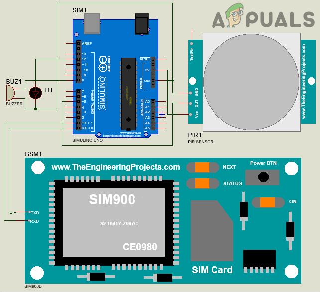
As we are using the PIR motion sensor to detect the motion in a particular area, the connection of this sensor with the Arduino board is pretty simple. The output pin of the PIR motion sensor is connected to the pin5 of the Arduino board. The Vcc and the ground pin of this sensor are connected to the 5V and ground of the Arduino board resp.comectively.
The connection of the GSM module with the Arduino board is established serially. The Tx pin and the Rx pin of the GSM module are connected to the Rx pin and the Tx pin of the Arduino board respectively.
While uploading the code on Arduino, make sure that the GSM is disconnected from the Arduino board.
Step 5: Getting Started With Arduino
Arduino IDE is a software on which you can write, debug, and compile a code that will run on an Arduino microcontroller. This code will be uploaded to the microcontroller through this IDE. IF you have no previous experience with this software, there is nothing to worry about because the whole procedure to use this software is given below.
- If you don’t have the software already installed, click here to download the software.
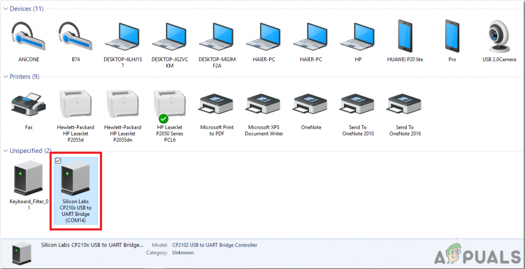
- Connect your Arduino board to the PC and open Control Panel. Click on Hardware and Sound. Now open Devices and Printer and find the port to which your board is connected. This port is different on different computers.
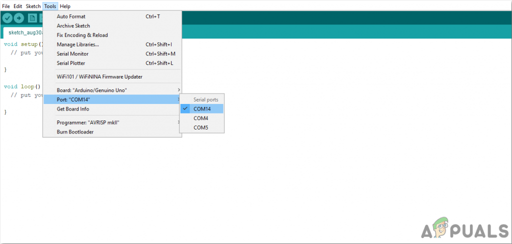
Finding Port - Now open the Arduino IDE. From Tools, set the Arduino board to Arduino / Genuino UNO.

Setting Board - From the same Tool menu, set the port number. This port number should be exactly the same as the port number that was observed before in the control panel.
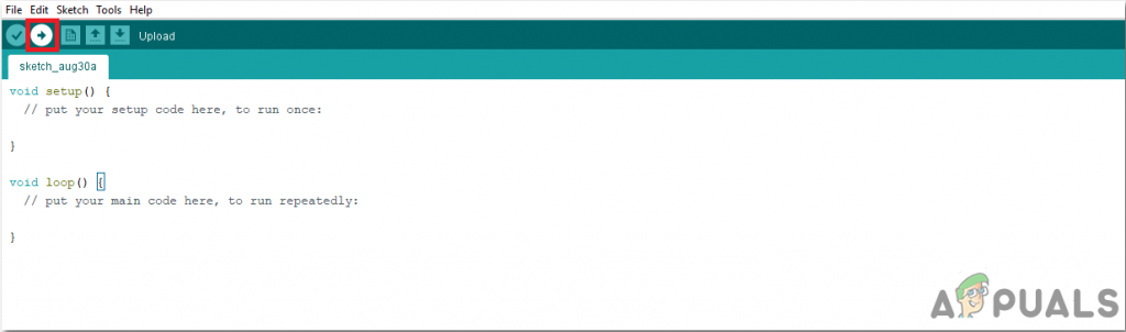
Setting Port - Download the code attached below and copy it to your IDE. To upload the code, click on the upload button.
Upload
- Download the code attached below and copy it to your IDE. To upload the code, click on the upload button.
- To download the code, click here.
Step 6:Code
The Code is very simple and well commented. Although it is very simple to understand, it is briefly explained below:
1. AT the start, Pins of Arduino are initialized that will be connected to the buzzer, led and the PIR motion sensor. LED will be connected to pin12 of Arduino, Buzzer will be connected to pin8 of the Arduino and the PIR motion sensor’s output pin will be connected to pin5 of Arduino Uno.
int led=12;      // coonnect lled to pin12 of Arduino
int buzzer=8;    // connect led to pin8 of Arduino
int pirOutput=5; // connect output of PIR sensor to pin5 of Arduino
2. void setup() is a function that is executed only once in a program. It only runs when the microcontroller is turned on or the enable button is pressed. Baud rate is set in this function using the Serial. begin command. Baud rate is actually the speed in bits per second by which microcontroller communicates with the external components attached. Then the pin of the microcontroller that is used, is declared to be used as OUTPUT. In the end, a LOW signal is sent to the LED, buzzer and the PIR motion sensor’s output pin.
void setup()
{
 Serial.begin(9600);          //set the baud rate
 pinMode(led,OUTPUT);         // declare led pin as OUTPUT pin
 pinMode(buzzer,OUTPUT);      // declare buzzer pin as OUTPUT pin
 pinMode(pirOutput,INPUT);    // declare PIR sensor pin as OUTPUT pin

 digitalWrite(pirOutput,LOW); // initially send a LOW signal to the PIR sensoor output pin
 digitalWrite(led,LOW);       // turn the LED off
 digitalWrite(buzzer,LOW);    // turn the buzzer off
}
3. void loop() is a function that runs repeatedly in a loop. In this function, the output pin of the PIR sensor is checked continuously. If the pin shows a HIGH signal, which means that the motion is detected, the led and the buzzer will turn on and an SMS will be sent to the mobile number that is specified in the code. After sending the SMS, it will wait for two seconds and then call the specified phone number.
void loop()
{
 if(digitalRead(pirOutput)==HIGH)                                    // if motion is detected
 { your
  digitalWrite(led,HIGH);                                            // turn on the LED
  digitalWrite(buzzer,HIGH);                                         // turn on the buzzer
  Serial.println("OK");                                              // print OK on serial Monitor
  delay(1000);                                                       // wait for one seconds
  Serial.print("AT+CMGF=1\r");                                       // set the GSM module to send SMS
  delay(1000);                                                       // wait for one second
  Serial.print("AT+CMGS=\"+xxxxxxxxxxx\"\r");                        // replace xxxxxxxxxx with your mobile number
  Serial.print("Intruder Alert - Someone has entered your Home \r"); // send this message on the specified mobile number
  Serial.write(0x1A);                                                // ASCII code for CTRL+Z (end of message)
  delay (2000);                                                      // wait for two seconds
  Serial.println("ATD+91xxxxxxxxxx;");                               // replace xxxxxxxxxx with your mobile number to call
  Serial.println("ATH");
 }
}
So this was the whole procedure to make an intruder alarm bu integrating a PIR motion sensor and a GSM module with the Arduino Uno microcontroller board. Now you can follow the above steps and enjoy making your own intruder alarm very easily at home.


