How To Make A DIY Arduino and Bluetooth Controlled Robotic Arm?
In the recent century, Robotics is the most emerging field of research. Robots have taken control of almost everything that humans used to do. We can see autonomous robots performing various tasks in our society. There are some remote controlled Robots also that help us to carry out various operations. From making Nano circuits in the field of engineering to taking out complex surgeries in the field of medical, robots are more reliable than human beings.
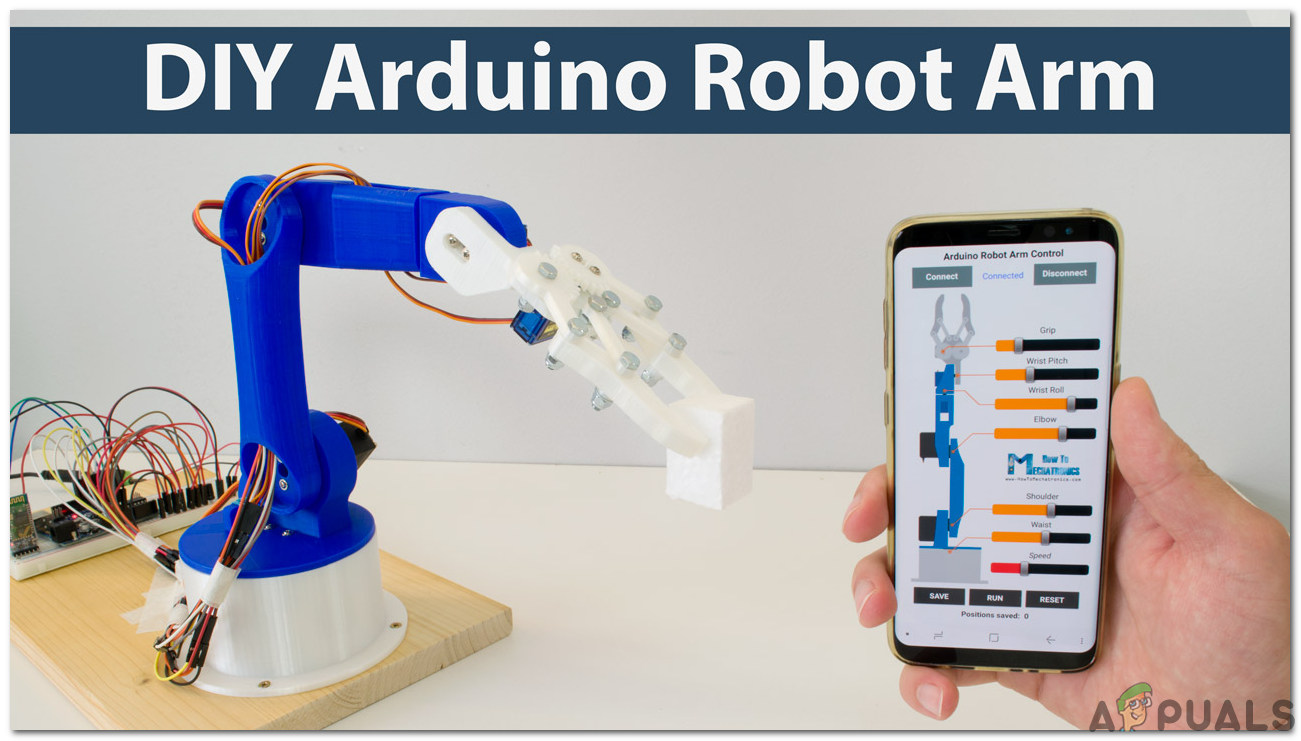
In this project, we are going to make a Robotic Arm that will be controlled by an Arduino microcontroller. It will be controlled via Bluetooth with the help of an android remote control app.
How To Control a Robotic Arm Using Arduino?
Now as we know the abstract of our project. Let us gather some more information about the circuitry and start building a Bluetooth controlled robotic arm and control it via Bluetooth.
Step 1: Collecting The Components
The best approach to start any project is to make a complete list of components. This is not only an intelligent way to start a project but it also saves us from many inconveniences in the middle of the project. A list of components of this project is given below:
- No products found.
- HC-05 Wireless Bluetooth Serial Transceiver
- No products found.
- 6V Adapter
- Jumper Wires
- No products found.
Step 2: Studying The Components
As we have a complete list of all the components that we are going to use, let’s move a step ahead and go through a brief study of all the components.
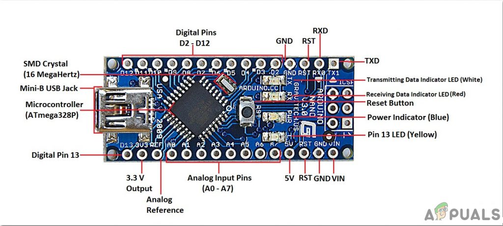
Arduino Nano is a microcontroller board that carries out various operations in different circuits. It requires a C Code that tells the board what tasks to perform and how. It has 13 digital I/O pins which mean that we can operate 13 different devices. Arduino Nano has exactly the same functionality as Arduino Uno but in quite a small size. The microcontroller on the Arduino Nano board is ATmega328p.If you want to control more than 13 devices, use Arduino Mega.
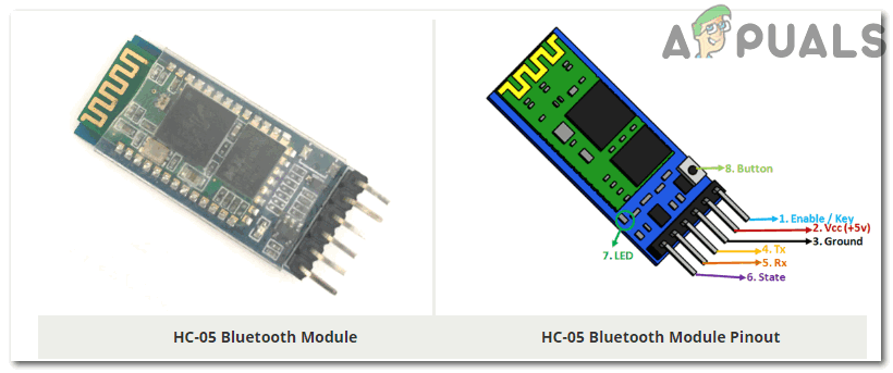
HC-05 Wireless Bluetooth Serial Transceiver: We need wireless communication in this project, so we will use Bluetooth technology and for that module that will be used is HC-05. This module has several programmable baud rates but the default baud rate is 9600 bps. It can be configured as either master or slave, whereas another module HC-06 can work only in slave mode. This module has four pins. One for VCC (5V) and the remaining three for GND, TX, and RX. The default password of this module is 1234 or 0000. If we want to communicate between two microcontrollers or communicate with any device with Bluetooth functionality like a Phone or Laptop HC-05 helps us to do that. Several Android applications are already available which makes this process a lot easier.
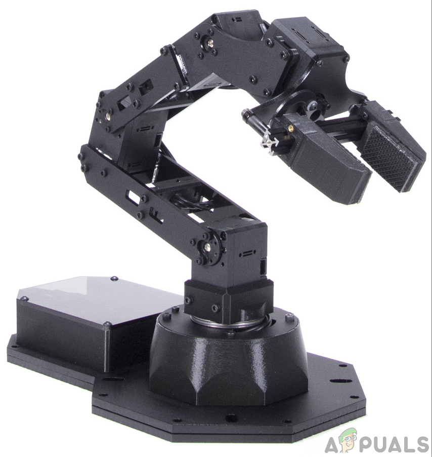
A typical Robotic Arm is made up of several segments and usually have 6 joints in it. It contains a minimum of 4 stepper motors which are controlled by the computer. Stepper motors are different from other DC motors. They move precisely in exact increments. These robotic arms are used to carry out various operations. We can operate them manually through a remote control or we can program them to work autonomously.
Step 3: Assembling The Components
Now as we know about the working of all the main components used. Let’s start assembling them and make a circuit to build a remote-controlled robotic arm.
- .Attach the Arduino Nano board on the breadboard. The Arduino will be powered through the positive and negative wire of the adapter.
- Place the Bluetooth module on the breadboard too. Power up the Bluetooth module through Arduino. Connect the Tx pin of the Bluetooth module to the Rx pin of the Arduino Nan board and connect the Rx pin of the Bluetooth module to the Tx pin of the Arduino Nano board.
- As we know that there are 4 stepper motors. Each one has a technical name. They are called Elbow, Shoulder, Base, and Gripper. The Vcc and Ground of all the motors will be common and connected to the positive and negative of the 6V adapter. The Signal pin of all the four motors will be connected to pin5, pin6, pin9, and pin11 of Arduino Nano.
- Make sure that the connections you have made are according to the following circuit diagram.
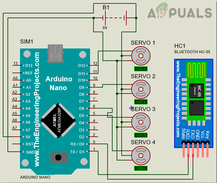
Circuit Diagram
Step 4: Getting Started With Arduino
If you are not already familiar with the Arduino IDE, don’t worry because a step by step procedure to set-up and use Arduino IDE with a microcontroller board is explained below.
- Download the latest version of Arduino IDE from Arduino.
- Connect your Arduino Nano board to your laptop and open the control panel. Then, click on Hardware and Sound. Now, click on Devices and Printers. Here, find the port to which your microcontroller board is connected. In my case it is COM14 but it is different on different computers.

Finding Port - Click on the Tool menu and set the board to Arduino Nano from the drop-down menu.
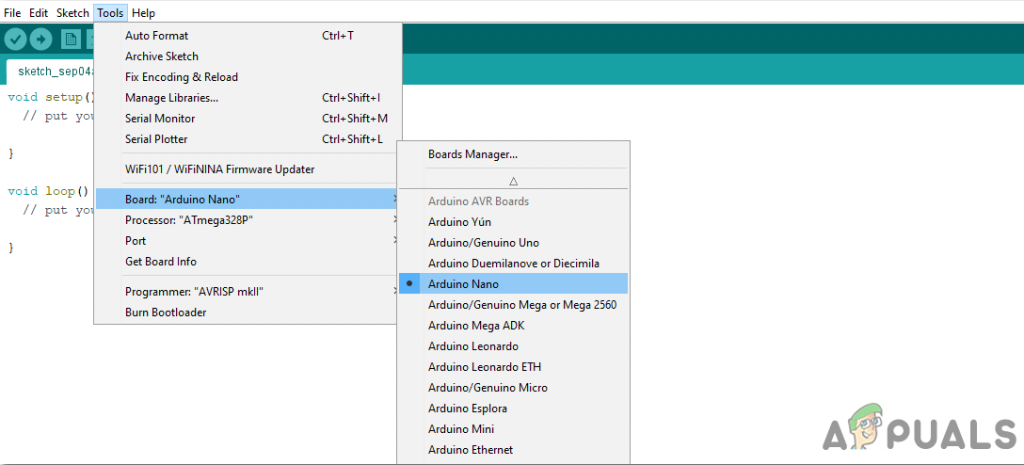
Setting Board - In the same Tool menu, set the port to the port number that you observed before in the Devices and Printers.

Setting Port - In the same Tool menu, Set the Processor to ATmega328P (Old Bootloader).
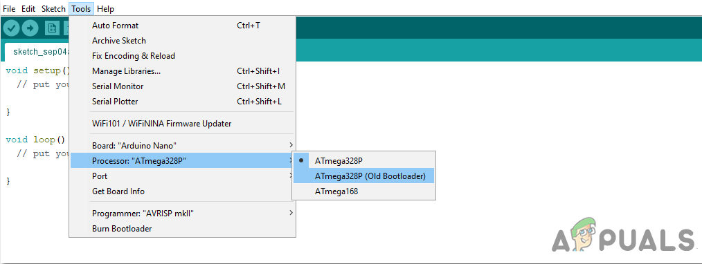
Processor - To write code to operate the servo motors, we need special library that will help us to write several functions for servo motors. This library is attached along with the code, in the link below. To include the library, click on Sketch > Include Library > Add ZIP. Library.
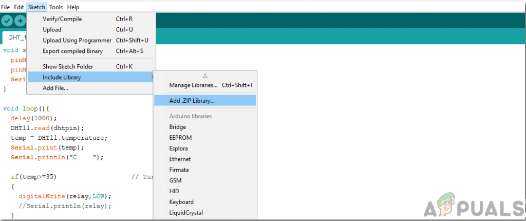
Include Library - Download the code attached below and paste it into your Arduino IDE. Click on the upload button to burn the code on your microcontroller board.
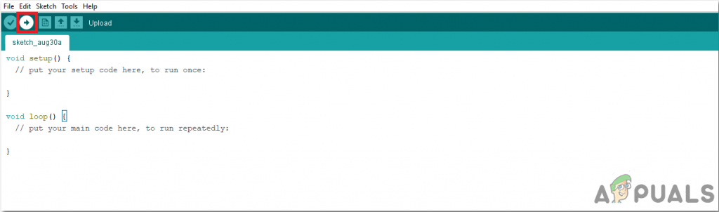
Upload
To download the code, click here.
Step 5: Downloading The App
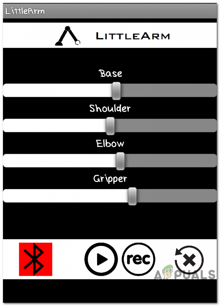
As we have now assembled the whole circuitry and uploaded the code in the microcontroller board. lets download a mobile app that will work as a remote control for the robotic arm. A free app is available on the google play store. The name of the app is the Little Arm Robot Control. To make a Bluetooth connection, turn on the Bluetooth on your mobile. Go to the settings and pair your mobile with the HC-05 module. After doing this, press the Bluetooth button in the app. If it turns green, it means that the app is now connected and ready to operate the robotic arm. There are sliders to set operate the robotic arm as desired.
Step 6: Understanding the Code
The code is well commented and easy to understand. Bur still, it is briefly explained below.
1. In the start, A library is included to write a code to operate servo motors. Another library math.h is included to perform different mathematical operations in the code. Four objects are also initialized to be used for the four servo motors.
#include <Servo.h> //arduino library
#include <math.h> //standard c library

#define PI 3.141

Servo baseServo;
Servo shoulderServo;
Servo elbowServo;
Servo gripperServo;

int command;
2. Then a structure is declared to take values for the base, shoulder, and elbow servo motors.
struct jointAngle{ // declairing a structure
int base;
int shoulder;
int elbow;
};
3. After this, some variables are initialized to store the desired grip, delay, and position of the servo motor. the speed is set to be 15, and an object is made to take the value of the angle in the structure.
int desiredGrip;
int gripperPos;

int desiredDelay;

int servoSpeed = 15;
int ready = 0;

struct jointAngle desiredAngle; //desired angles of the servos
4. void setup() is a function that is used to set the pins of Arduino as INPUT or OUTPUT. Here in this function, we have declared that the pin of the motors will be connected to which pins of the Arduino. It is also ensured that the Arduino doesn’t read serial input for too long. Initial Position and Baud Rate is also set in this function. Baud Rate is the speed by which the microcontroller board will communicate with the servos and Bluetooth module attached.
void setup()
{
Serial.begin(9600);
baseServo.attach(9); // attaches the base servo on pin 9 to the servo object
shoulderServo.attach(10); // attaches the shoulder servo on pin 9 to the servo object
elbowServo.attach(11);  // attaches the elbow servo on pin 9 to the servo object
gripperServo.attach(6);  // attaches the gripper servo on pin 9 to the servo object

Serial.setTimeout(50); //ensures the the arduino does not read serial for too long
Serial.println("started");
baseServo.write(90); //intial positions of servos
shoulderServo.write(150);
elbowServo.write(110);
ready = 0;
}
5. servoParallelControl() is a function that is used to detect the current position of the robotic arm and move it according to the command given through the mobile app. If the current position is less than the actual, the arm will move up and vice versa. This function will return the value of the current position and the speed of the servo.
int servoParallelControl (int thePos, Servo theServo, int theSpeed ){

 int startPos = theServo.read(); //read the current pos
 int newPos = startPos;
 //int theSpeed = speed;

 //define where the pos is with respect to the command
 // if the current position is less that the actual move up
 if (startPos < (thePos-5)){
  newPos = newPos + 1;
  theServo.write(newPos);
  delay(theSpeed);
  return 0;
  }
  else if (newPos > (thePos + 5)){
   newPos = newPos - 1;
   theServo.write(newPos);
   delay(theSpeed);
   return 0;
   }
   else {
    return 1;
   }
}
6. void loop() is a function that runs repeatedly in a loop. This function reads the data coming serially and store the angle of each servo in the structure. Initially, the status of all the servos is set to zero. Here a function servoParallelControl() is called and parameters are passed in it. this function will return the value and it will be stored in a variable of status.
void loop()
{
 if (Serial.available()){
 ready = 1;
 desiredAngle.base = Serial.parseInt();
 desiredAngle.shoulder = Serial.parseInt();
 desiredAngle.elbow = Serial.parseInt();
 desiredGrip = Serial.parseInt();
 desiredDelay = Serial.parseInt();

 if(Serial.read() == '\n'){

 Serial.flush(); //clear all other commands piled in the buffer
 //send completion of the command
 Serial.print('d');
 }
}

int status1 = 0;
int status2 = 0;
int status3 = 0;
int status4 = 0;
int done = 0 ;

while(done == 0 && ready == 1){
 //move the servo to the desired position
 status1 = servoParallelControl(desiredAngle.base, baseServo, desiredDelay);
 status2 = servoParallelControl(desiredAngle.shoulder, shoulderServo, desiredDelay);
 status3 = servoParallelControl(desiredAngle.elbow, elbowServo, desiredDelay);
 status4 = servoParallelControl(desiredGrip, gripperServo, desiredDelay);

  if (status1 == 1 & status2 == 1 & status3 == 1 & status4 == 1){
  done = 1
  }
 }// end of while
}
Now, this was the whole procedure of making a robotic arm. After burning the code and downloading the app, the robot should work perfectly fine when the sliders on the app are moved. You can also program the arm to work autonomously to perform the desired task.


can i use this programming in Arduino uno????