How To Maintain Constant Temperature For Chickens In Poultry Huts Using A Light Bulb?
The essential task in any poultry farm is to maintain a constant warm temperature for chicks. Most of the poultry farms have small huts in which they keep their chicks and eggs. The temperature must be warm to ensure the health of these chicks. This can be done by applying high energy bulbs in those huts. These bulbs produce heat energy which is needed to keep the temperature high in these huts.
How to Use a Light Bulb To Maintain Warm Temperature?
As we have read the abstract of our project. Let us gather some more information and start making this project.
Step 1: Collecting the Components
The best approach to start any project is to make a list of all the components at the start and a good plan to work on it. The following are the components that we are going to use in this project.
- No products found.
- No products found. – Temperature and Humidity Sensor
- Relay Module
- Breadboard
- No products found.
- Bulb
Step 2: Studying the Components
Now as we have made a list of all the components that we are going to use in this project. Let us move a step further and go through a brief study of all the main components.
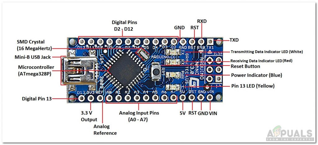
Arduino nano is a microcontroller board that is used to control or carry out different tasks in a circuit. We burn a C Code on Arduino Nano to tell the microcontroller board how and what operations to perform. Arduino Nano has exactly the same functionality as Arduino Uno but in quite a small size. The microcontroller on the Arduino Nano board is ATmega328p.
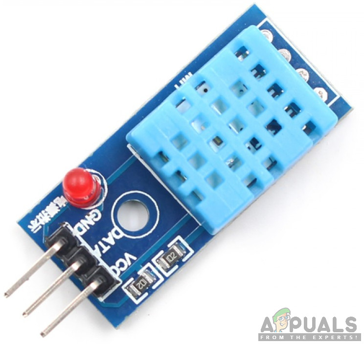
DHT11 is a temperature and humidity sensor. Its temperature range is 0 to 50-degree Celsius. It is a low cost and an efficient sensor that gives high stability. To measure the temperature it has a built-in thermistor. It also measures the humidity but in this project, we don’t need to measure humidity.
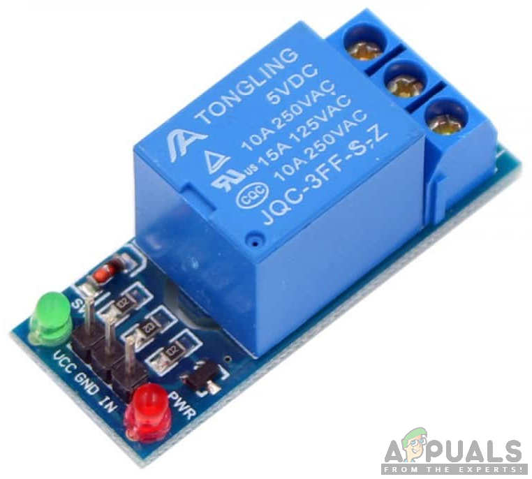
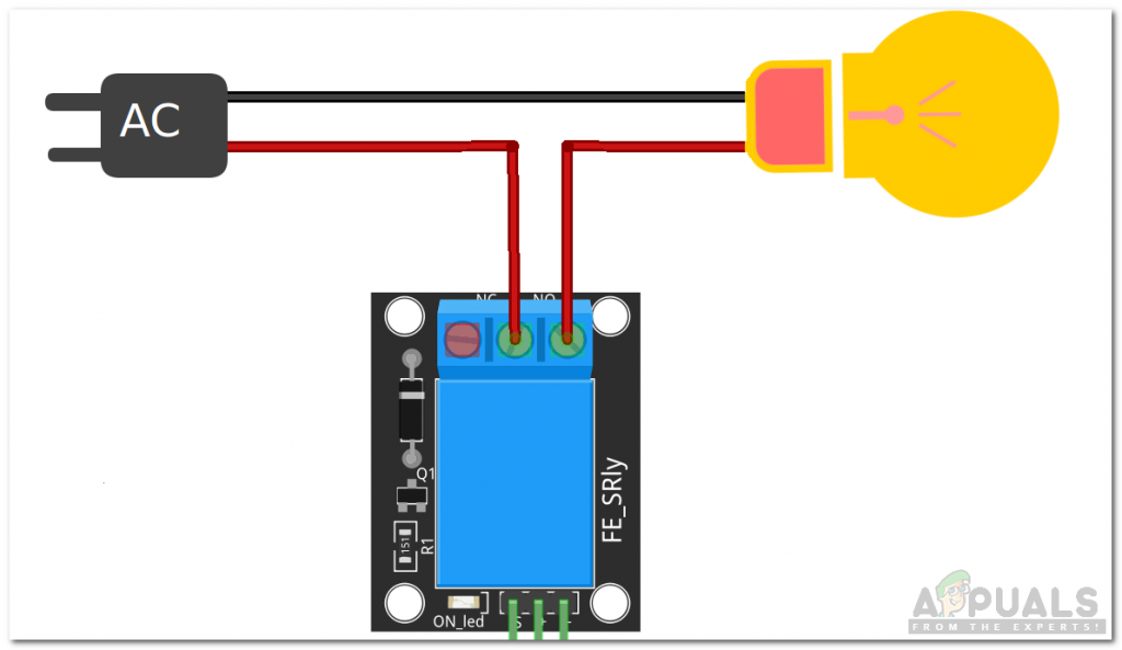
A relay module is a switching device that takes input from Arduino and switches accordingly. It operates in two modes, Normally Open (NO) and Normally Closed (NC). In the NO oped, the circuit is broken unless a HIGH signal is applied to the relay module. In NC mode, the circuit is complete unless a HIGH signal is applied to the relay module.
Step 3: Assembling the Components
As we have gone through a brief study of how all the components work. Let us start assembling all the components to make a final product.
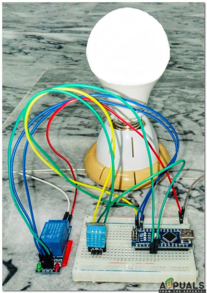
Connect the Vcc and ground pin of the DHT11 sensor to the 5V and ground of the Arduino nano. Connect the output pin of the DHT11 sensor to the Pin2 and the IN pin of the relay module to the Pin3 of the Arduino. Power up the relay module through Arduino and connect the positive wire of the bulb in the NO pin of the relay module. Be careful while connecting the relay module to the bulb. Make sure your connection of the bulb to the relay looks like shown below.
Step 4: Getting started with Arduino
If you are not already familiar with the Arduino IDE, don’t worry, you are explained how to use Arduino IDE below.
- Download the latest version of Arduino from Arduino.
- Connect your Microcontroller board to your Laptop.
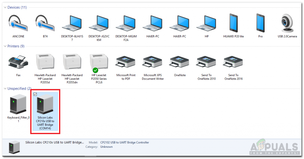
- Go to Control Panel and click on Hardware and Sound. Now Click on Devices and Printers. Here, find the port to which your Arduino is connected. In my case it is COM14 but it is different on different computers.
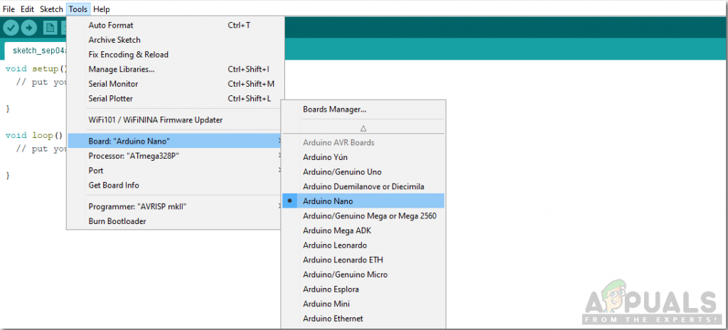
Finding Port - Click on the Tool menu and set the board to Arduino Nano.
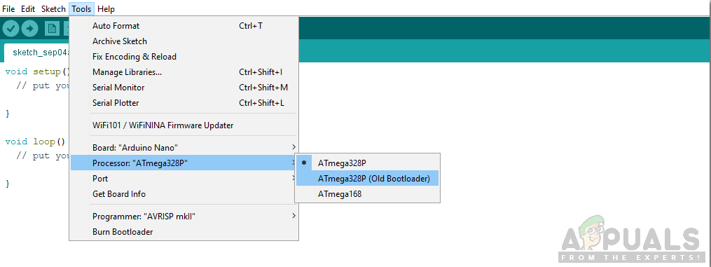
Setting Board - From the same Tool menu, set the Processor to ATmega328p (Old Bootloader).
Setting Processor - Now set the port that you observer back in the control panel.
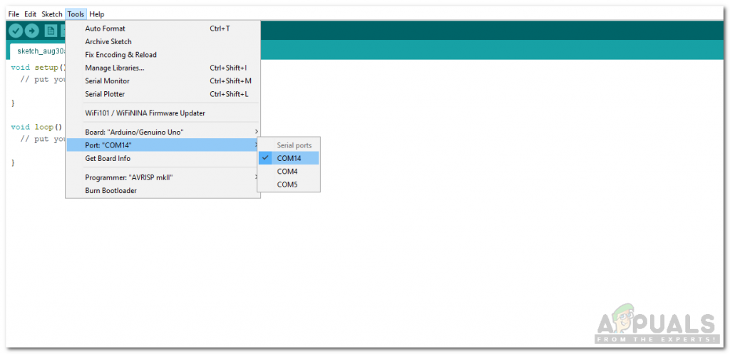
Setting Port - We will have to include a library to use the DHT11 sensor. The library is attached below in the download link along with the code. Go to Sketch > Include Library > Add .ZIP Library.
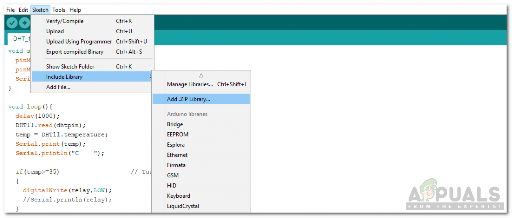
Including Library - Download the code attached below and copy it to your IDE. Click on the upload button to burn the code on your microcontroller board.
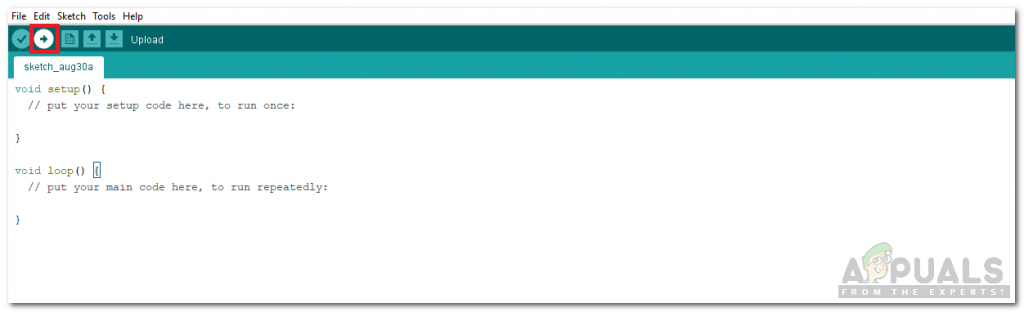
Upload
You can download the code by clicking here.
Step 5: Code
The code for the DHT11 sensor is well commented and self-explanatory but here is some explanation of the code.
- At the start, the library to use DHT11 is included, variables are initialized and pins are also initialized.
#include <dht11.h>
dht11 DHT11;
#define dhtpin 2
#define relay 3
float temp;
2. void setup() is a function that is used to set the pins as INPUT or OUTPUT. It also sets the baud rate of the Arduino. Baud rate is the communication speed of the microcontroller board.
void setup(){
 pinMode(dhtpin,INPUT);
 pinMode(relay,OUTPUT);
 Serial.begin(9600); // baud rate
}
3. void loop() is a function that runs again and again in a cycle. In this function, we are reading the data from the output pin of DHT11 and switching the relay on or off at a certain temperature level.
void loop(){
 delay(1000);
 DHT11.read(dhtpin); // Read the data from DHT sensor
 temp = DHT11.temperature; // Convert this data to temerature and store it in temp
 Serial.print(temp); // Show the temperature on serial moonitor
 Serial.println("C ");

 if(temp>=35) // Turn the fan on
 {
  digitalWrite(relay,LOW);
  //Serial.println(relay);
 }
 else // Turn the fan off
 {
  digitalWrite(relay,HIGH);
  //Serial.println(relay);
  }
}
Now as you have learned how to automate a bulb to maintain a constant warm temperature in poultry huts for your chickens and eggs, you can now start working on this project. You can also use this DHT11 sensor in other projects, for example, Fire alarms, Smart homes, Room Automations, etc.


