How To Design Voice Activated Home Automation?
The idea of Home Automation is picking up prominence as it helps in lessening human exertion and mistakes and hence expanding the effectiveness. It utilizes a combination of equipment and programming advancements that enable control over machines and other electronic gadgets inside a home. With the help of Home Automation, we can control our electrical appliances remotely and a big advantage is that power consumption is reduced to a great extent. There are several types of Home Automation like Bluetooth Controlled, Remote Controlled and Internet Controlled etc and each of them has their advantages and disadvantages. In this project, we will design a Voice Controlled Home Automation where different appliances will be controlled by sending the voice command. This system is very expensive when bought from the market but when we integrate all these appliances through Arduino, it becomes very easy and low-cost to control all the home electrical appliances.
How To Automate Home Appliances Using Arduino?
As we have the basic idea, now let’s move towards gathering the components, assembling them to make a circuit and writing the code to automate your home appliances.
Step 1: Components Used (Hardware)
- Arduino Uno
- HC-05 Bluetooth Module
- No products found.
- 12V Relay Module
- No products found.
- No products found.
- No products found.
- No products found.
- No products found.
Step 2: Components Used (Software)
- Proteus 8 Professional (Can be downloaded from Here)
After downloading the Proteus 8 Professional, design the circuit on it. We have included software simulations here so that it may be convenient for beginners to design the circuit and make appropriate connections on the hardware.
Step 3: Studying The Components
As we have made a list of components that we are going to use in our project. Let us move a step ahead and go through a brief study of how these components work.
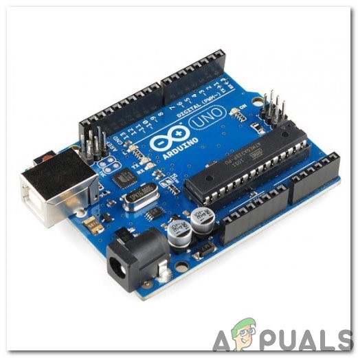
- Arduino UNO: The Arduino UNO is a microcontroller board which comprises of a microchip ATMega 328P and is developed by Arduino.cc. This board has a set of digital and analog data pins that can be interfaced with other expansion boards or circuits. This board has 14 Digital pins, 6 Analog pins, and programmable with the Arduino IDE (Integrated Development Environment) via a type B USB cable. It requires 5V to power ON and a C Code to operate.
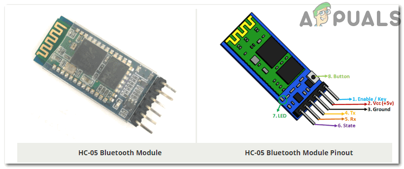
Arduino UNO - HC-05 Wireless Bluetooth Serial Transceiver: We need wireless communication in this project, so we will use Bluetooth technology and for that module that will be used is HC-05. This module has several programmable baud rates but the default baud rate is 9600 bps. It can be configured as either master or slave, whereas another module HC-06 can work only in slave mode. This module has four pins. One for VCC (5V) and the remaining three for GND, TX, and RX. The default password of this module is 1234 or 0000. If we want to communicate between two microcontrollers or communicate with any device with Bluetooth functionality like a Phone or Laptop HC-05 helps us to do that. Several android applications are already available which makes this process a lot easier.
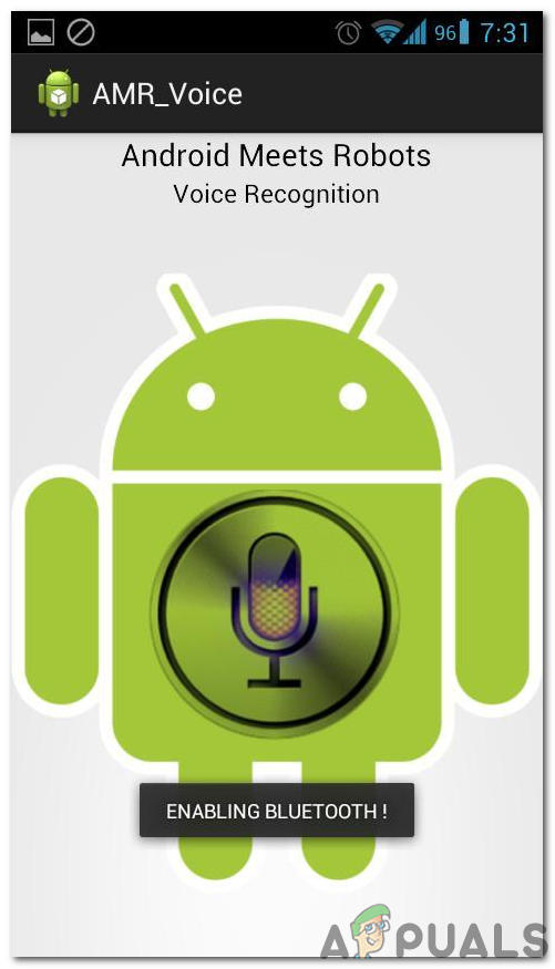
HC-05 Bluetooth Module - Bluetooth Voice Control for Arduino: This app is developed by SimpleLabsIN for voice-based Arduino projects. This Android Application will use the phone’s voice recognition feature and will convert the voice commands to text and transfer the string via Bluetooth. The application can be downloaded from Here
BT Voice Control App - 12 V Relay Module: If anyone wants to switch high voltage loads from a microcontroller, this 12V relay board can do it. It contains 8 x 12V relays rated at 10A/250V AC (DC 30V/10A). Each relay module is switched on/off by an opto-isolated digital input that can be connected directly to a microcontroller output pin. It only requires a voltage of approx 1.0V to switch the inputs on but can handle input voltages up to 12V. This makes it ideal for both 5V and 3.3V devices. You can purchase the relay module according to your number of appliances you want to control. For example, if you want to control 4 appliances you should buy 4 Relay module.
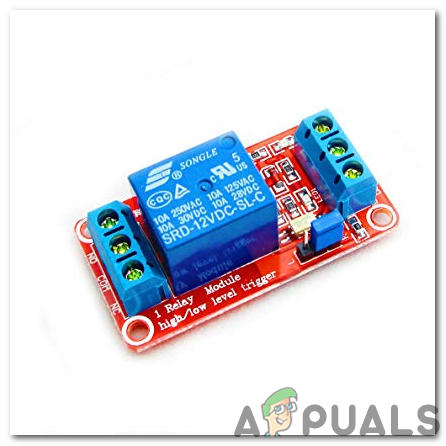
12V Relay Module
Step 4: Understanding Circuit Design With Circuit Diagram
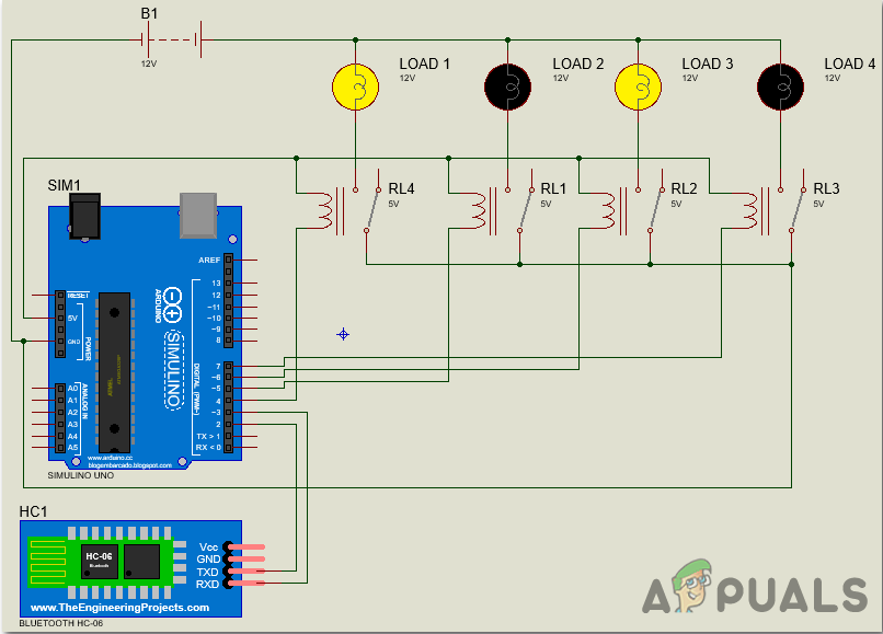
Firstly, we need to connect HC-05 with Arduino UNO. Since Bluetooth uses the UART protocol, we need to use the RX and TX pins of the Arduino. We will be using the “SoftwareSerial” library to define our own RX and TX pins (Pin 2 is RX and Pin 3 is TX). The RX pin of the Bluetooth module and the TX pin of the Arduino will be disconnected. Secondly, we will connect the relays to the Arduino. We have used a readymade relay board with 4 – channels, so we need to connect the inputs of the individual relays to the Arduino. For connecting load to the relay module refer to the diagram below:
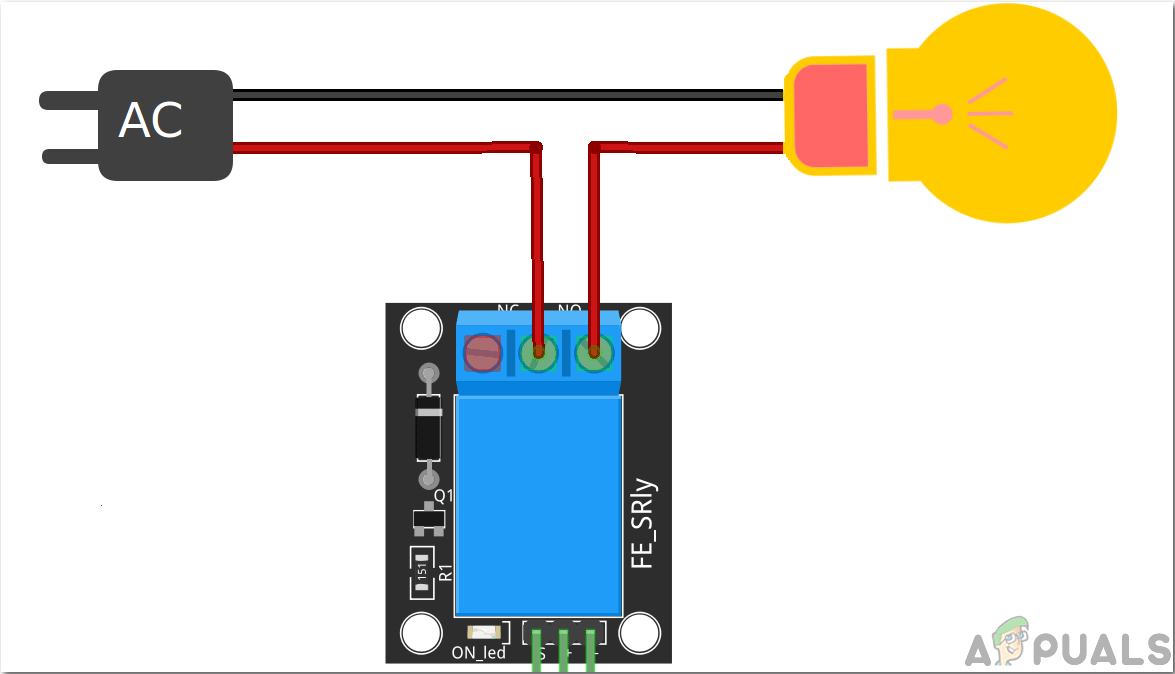
Four loads are connected to the relay module for demonstration and be extra careful while using AC Mains with a relay board. Just for demonstration, we have switched ON the alternate loads:
Step 5: Working Principle Of The Project
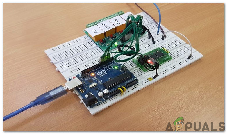
In this project, voice commands are used to control different appliances. Assemble the hardware according to the circuit diagram given above. Assemble all of the components on the breadboard. After making the necessary connections, switch on the power supply to the circuit and pair the phone’s Bluetooth to the HC-05 Bluetooth module. Before pairing install the application mentioned above in your smartphone.
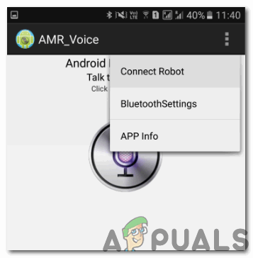
Now, connect the phone with the Bluetooth module. Click on the option “Connect Robot” and select the appropriate Bluetooth device. If the devices aren’t paired earlier, pair them now by entering the pin 0000 or 1234.
After a successful connection, devices are ready to transmit data. For transmitting data, press the microphone icon on the app and start giving voice commands. Ensure that the voice recognition feature is enabled on your smartphone (this is usually associated with Google app). For example, when we press the microphone icon and say “Turn on the light”, the application will recognize the command and transfer it to the Bluetooth module.
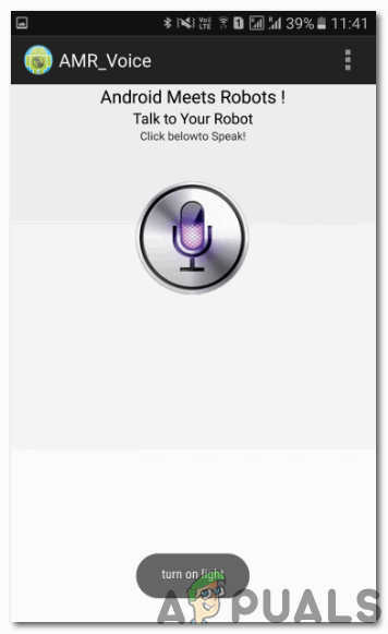
When the string is recognized by the application it will send the string as “turn on light#’ and the actual message received by the Bluetooth Module has this type of format (“*Message#”). The reason for padding the ‘*’ and ‘#’ at the begging and end of the string is to identify the starting and end of the message. The received message is compared with some predefined strings and if the message matches with them the corresponding action like “turning on” and turning off happens.
In this project we have used the following commands: “turn on AC”, “turn off AC”, “turn on light”, “turn off light”, “turn on TV”, “turn off TV”, “turn on fan”, “turn on all” and “turn off all”.
Step 6: Getting Started With Arduino
If you are not familiar with Arduino IDE before, don’t worry because below, you can see clear steps of burning code on the microcontroller board using Arduino IDE. You can download the latest version of Arduino IDE from here and follow the steps mentioned below:
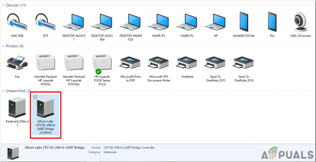
1). When the Arduino board is connected to your PC, open “Control panel” and click on “Hardware and Sound”. Then click on “Devices and Printers”. Find the name of the port to which your Arduino board is connected. In my case it is “COM14” but it may be different on your PC.
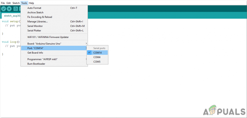
2). Now open the Arduino IDE. From Tools, set the Arduino board to Arduino / Genuino UNO.

3). From the same Tool menu, set the port number that you saw in the control panel.
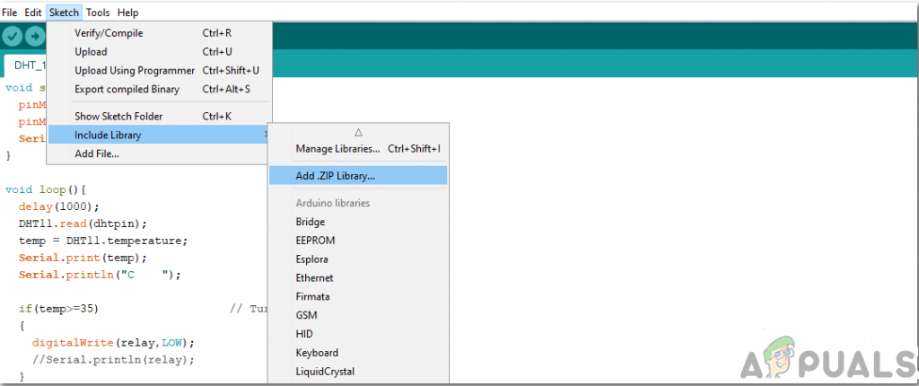
4). To use this voice-controlled app, we need a special library to be included in Arduino IDE. This Library is attached in the link below, along with the code. To include the library go to Sketch > Include Library > Add ZIP. Library.
5). Download the code attached below and copy it to your IDE. To upload the code, click on the upload button.
You can download the code by clicking here.
Step 7: Understanding the code
The Code is not so complex but still, some of its parts are briefly described below.
1. In the start, a library is included to allow serial communication on other digital pins of the Arduino, using software to replicate the functionality. Two Pins are initialized to be used with the Bluetooth module. Four Pins are initialized to be used for the home appliances connected to the system and a string variable is initialized to store the data coming through Bluetooth serially.
#include <SoftwareSerial.h>

const int rxPin = 2; // Initialize pisns for bluetooth module
const int txPin = 3;
SoftwareSerial mySerial(rxPin, txPin);

int ac=4; // Initialize Pins for Home Appliances
int light=5;
int fan=6;
int tv=7;
String data;
2. void setup() is a function in which we set the initialized pins to be used as INPUT and OUTPUT. Baud Rate is also initialized here. Baud Rate is the speed by which the Arduino board communicates with the components attached. In our function, we have set all the pins connected to the appliances to LOW.
void setup()
{
Serial.begin(9600);
mySerial.begin(9600);

pinMode(ac, OUTPUT);
pinMode(light, OUTPUT);
pinMode(fan, OUTPUT);
pinMode(tv, OUTPUT);

digitalWrite(ac, LOW);
digitalWrite(light, LOW);
digitalWrite(fan, LOW);
digitalWrite(tv, LOW);
}
3. void loop() is a function that runs repeatedly in a loop. Here all the conditions are set to make the system work properly. The following While() loop is used to take data that is coming serially to the microcontroller.
 while(1) // Getting input serially
{
while(mySerial.available()<=0);
ch = mySerial.read();
if(ch=='#')
break;
data+=ch;
}
Below all the conditions are set to switch on all the electrical appliances attached, as the user commands. These conditions are pretty simple and self-explanatory.
 if(data=="*turn on AC")
{
digitalWrite(ac,HIGH);
Serial.println("ac on");
}
else if(data=="*turn off AC")
{
digitalWrite(ac,LOW);
Serial.println("ac off");
}
else if(data=="*turn on light")
{
digitalWrite(light,HIGH);
Serial.println("light on");
}
else if(data=="*turn off light")
{
digitalWrite(light,LOW);
Serial.println("light off");
}
else if(data=="*turn on fan")
{
digitalWrite(fan,HIGH);
Serial.println("fan on");
}
else if(data=="*turn off fan")
{
digitalWrite(fan,LOW);
Serial.println("fan off");
}
else if(data=="*turn on TV")
{
digitalWrite(tv,HIGH);
Serial.println("tv on");
}
else if(data=="*turn on TV")
{
digitalWrite(tv,LOW);
Serial.println("tv off");
}
else if(data=="*turn on all")
{
digitalWrite(ac,HIGH);
digitalWrite(light,HIGH);
digitalWrite(fan,HIGH);
digitalWrite(tv,HIGH);
Serial.println("all on");
}
else if(data=="*turn off all")
{
digitalWrite(ac,LOW);
digitalWrite(light,LOW);
digitalWrite(fan,LOW);
digitalWrite(tv,LOW);
Serial.println("all off");

}
}
Applications
- The Voice-Activated Home Automation system will help us control different loads (electrical appliances) with simple voice commands.
- People who are disabled can get a lot of benefits from this project as if they are unable to walk around they can give a voice command and turn ON or OFF the appliance.
- This project can also be expanded by adding different sensors (light, smoke, etc.).


