How To Design Panic Alarm Circuit For Home?
There can be an uncertain situation at home and many times people living in the home are panicked. For example, when a fire breaks out at home and there are only children at home they are unable to inform anyone about the matter. During this type of situation, we might be unable to intimate the people around us so we will design a circuit of a panic alarm so that we could inform others about the scenario without any delay. We could place the push button at a reasonable distance to carry out quick action in silence by pressing a single button. An indication of an emergency can either be in the form of a visible or audible signal, which can be fixed at a few meters away through the wire. The sign of emergency can either be in the form of a visible or audible signal, which can be fixed at a couple of meters away through the wire.
How To Design Circuit Using 555 Timer?
Now, as we have the basic idea of the task let’s move towards collecting the components, designing the circuit on software for testing and then finally assembling it on hardware.
Step 1: Studying The Components.
Before the implementation of this project, we need to study the components.
- 555 Timer IC:
There are three main configurations of the 555 timer IC.
- Astable multivibrator.
- Monostable multivibrator.
- Bistable multivibrator.
In our project, we need two stable states. The first one is turning ON the alarm and the second one is turning OFF the alarm. In our case, we have configured our IC in Bistable mode. When we press SET mode the signal is sent to the location in audible form. For turning off the alarm we use the RESET button.
2. BC 547 Transistor:
The 555 Timer IC can only handle a few mA of current therefore we have used the BC 547 transistor which can handle a large amount of current. The BC547 can be replaced by some other NPN transistor part as per the voltage and current rating of the alarm and light utilized.
Step 2: Collecting The Components (Hardware)
- No products found.
- No products found.
- Buzzer (6-12V) x 1
- The LED x 1
- Tactile Switch
- No products found.
- Resistor 10k ohm x 2, 22ohm x 1, 1KὨ
- No products found.
- Breadboard x 1
Step 3: Installing The Necessary Software
Now, you need to install the below-mentioned software on your systems for running the simulation. Link is provided for downloading the software.
- Proteus 8 Professional – You can download Proteus from Here
Step 4: Designing The Circuit On Proteus
We will design the circuit on Proteus for testing and when we will press the SET button LED should turn ON and when we will press the RESET button LED should turn OFF. If this happens it means our circuit is working properly.
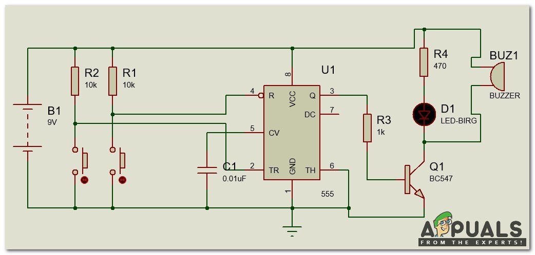
- Circuit Diagram Before Testing:
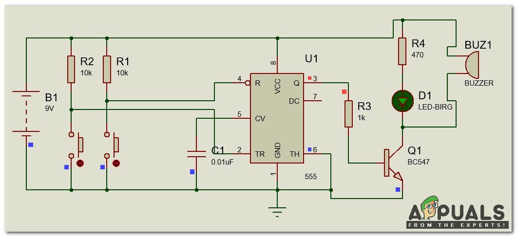
2. Circuit Diagram After Testing:
Step 5: Setting Up The Hardware
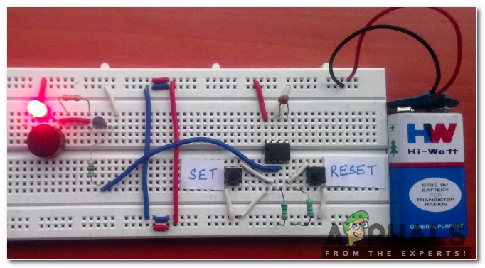
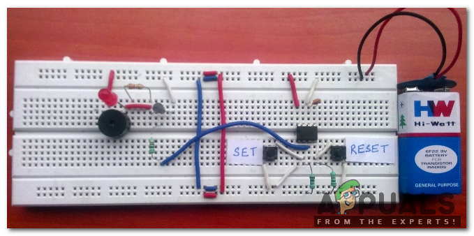
Now, as we have done the simulation and we know that our circuit is working properly, we will move towards the hardware setup. The circuit can be assembled on the Vero board as well or PCB. If somebody is using a Vero board or PCB he/she will need a soldering iron to attach the components on them. Join the components according to the circuit diagram shown above and then place the hardware at a suitable place. The preferred location is near to the gate of the house so that if any panic situation occurs a signal is sent immediately and neighbors or other people walking in the street come to know that the people living in the house need some kind of help. Circuit diagram with all the components assembled on the breadboard is shown below so that even if a person doesn’t know much about circuit analysis he/she should be able to do the connections accurately :
As we have assembled the hardware we should feel safe and secure now. Furthermore, it can be placed in the room of aged people living in our home so that if they want something or there is a state of emergency they can immediately inform the people living in the home.


