How to Automate Street Lights outside Your Home?
There are street lights outside our homes, on balconies or in gardens that need to be switched on or off manually. We can make a system using Arduino and an LDR which will switch these lights on at night time and switch them off at day time automatically without needing a person to go outside and switch them on or off manually.
How to Use Arduino to Automate the Lights?
Let us now start to collect some information about the project and start working.
Step 1: Collecting Components
Before we start working on the project, let’s make a list of components that we will use and study the working of those components.
- No products found.
- No products found.
- Breadboard / Veroboard
- No products found.
- No products found.
Step 2: Studying the Components
Arduino Uno is a microcontroller board controls various circuits. We tell it what to do by burning a C code on this board through Arduino IDE. If Arduino UNO is not available you can use Arduino NANO instead.
An LDR is a Light Dependent Resistor which varies its resistance with the intensity of light. An LDR module can have an Analog output pin, Digital output pin or both. the resistance of the LDR is inversely proportional to the intensity of light which means greater the intensity of light, lower the resistance of LDR. The Sensitivity of the LDR module can be changed by using a potentiometer knob on the module.
A relay module is a device that is used in a circuit for switching purposes. It works on two modes, Normally Open (NO) and Normally Closed (NC). When used in NO mode, the circuit is broken initially and when used in NC mode, the circuit is closed initially.
Step3: Making the Circuit
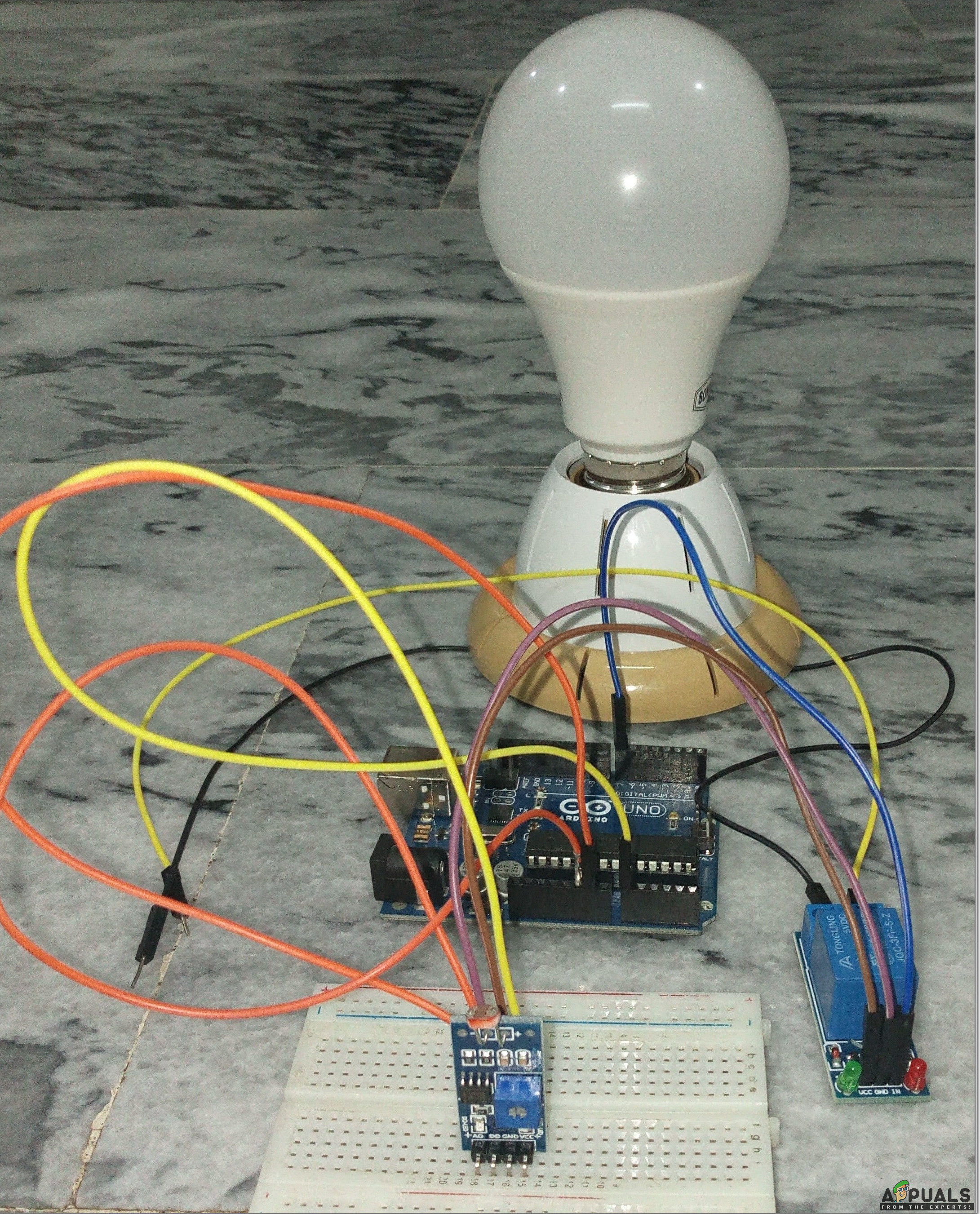
Now, as we know enough about the components that we are going to use in our project, let’s start making the circuit as shown below.
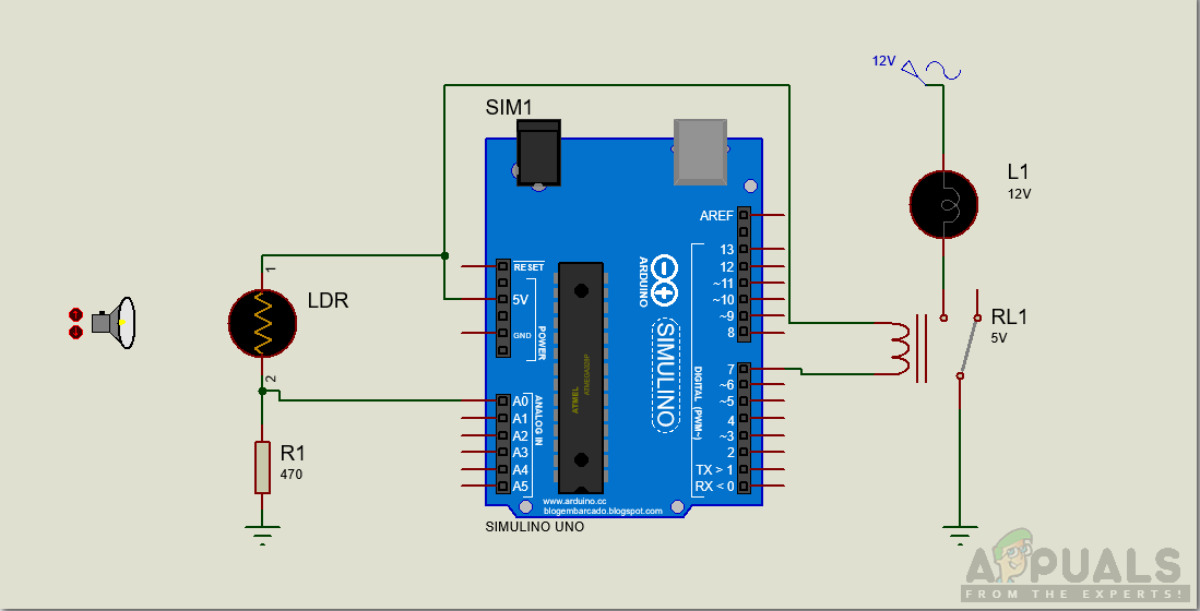
In this circuit, the A0 pin on the LDR module is connected to the A0 pin of the Arduino and the relay is connected to pin 7 of the Arduino. When the Light will fall on the LDR, it’s resistance will change and it will send some analog values to Arduino. Then Arduino will process these values and send a signal to the relay and will tell it to switch on or off. Both the relay and LDR module is powered by a 5V pin of Arduino. I have made the circuit on the breadboard but you can make this circuit on Veroboard aswell. On veroboard make sure you make tight connections using solder. After soldering, do not forget to run a continuity test.
Step 4: Getting Started with Arduino
If you are not familiar with Arduino IDE before, don’t worry because below, you can see clear steps of burning code on microcontroller board using Arduino IDE. Download the latest version odd Arduino IDE from Arduino and follow the steps below.
- When the Arduino board is connected to your PC, open “Control panel” and click on “Hardware and Sound”. Then click on “Devices and Printers”. Find the name of the port to which your Arduino board is connected. In my case it is “COM14” but it may be different on your PC.

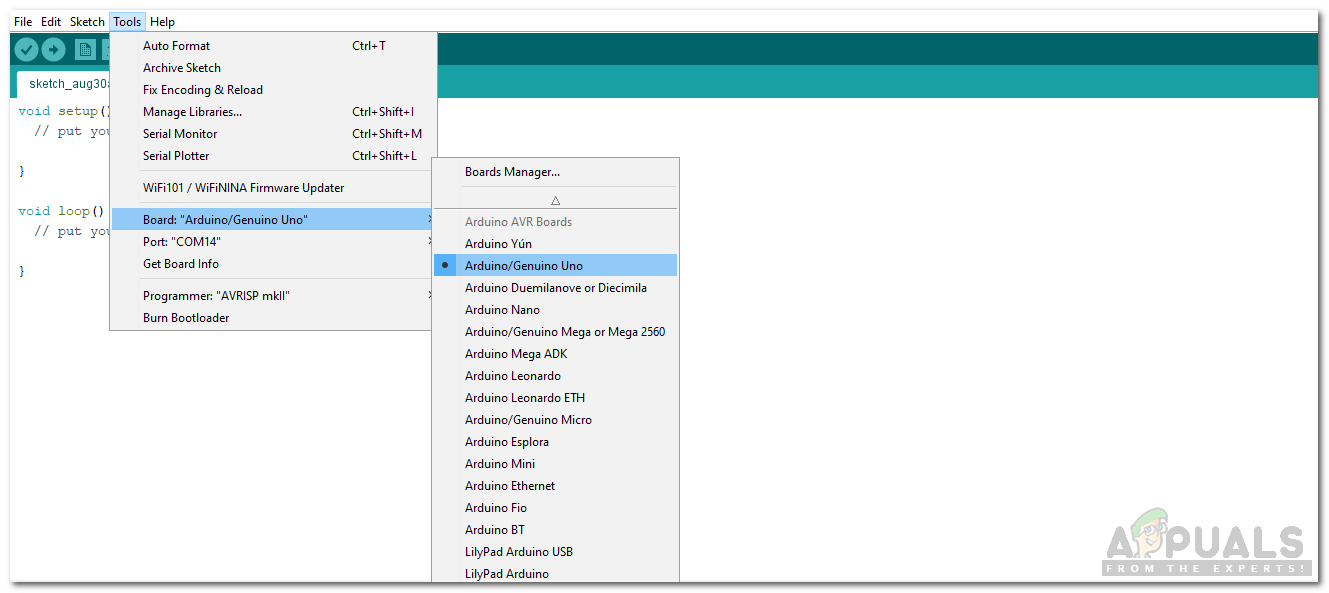
Find Port - Now open the Arduino IDE. From Tools, set the Arduino board to Arduino / Genuino UNO.
Setting Board - From the same Tool menu, set the port number that you saw in the control panel.
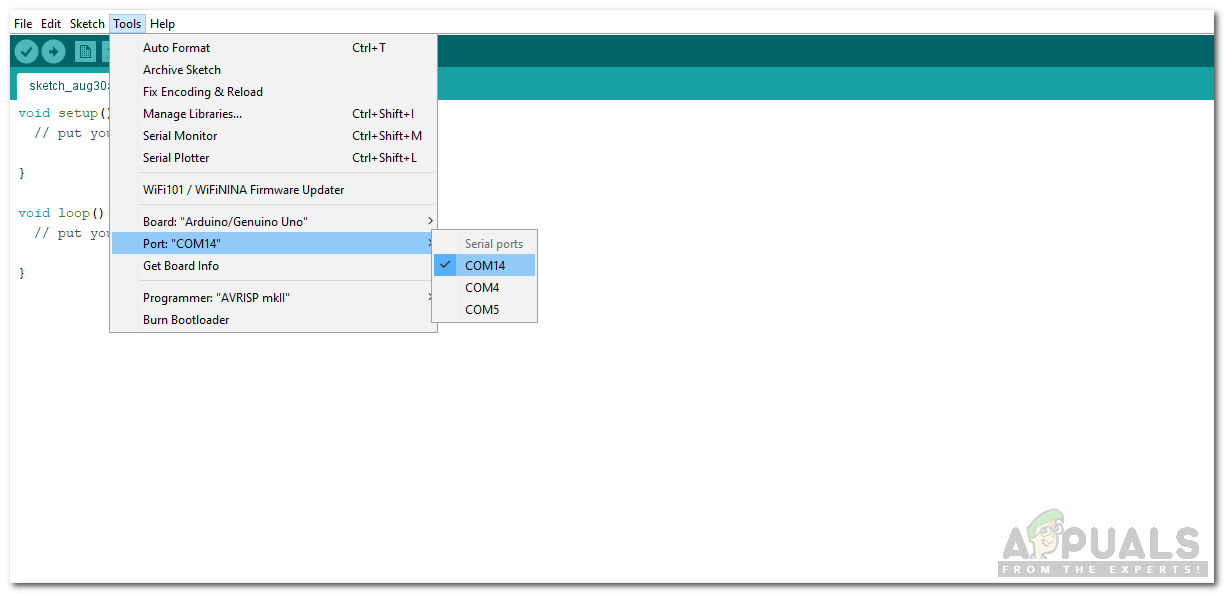
Setting Port - Copy the code here on the screen and upload it on your Arduino board.
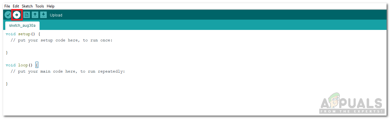
Upload
Step 5: Code
Download the code from Here
The code is very simple and self-explanatory, but some general explanation of the code is given below.
1). In the start, Pins are initialized that will be used in the code.
const int R1 = 7; //Relay
const int ldrPin = A0; //LDR pin
2). void setup() is a function which the pins to be used as OUTPUT or INPUT. It also sets the baud rate of the microcontroller board. Baud rate is the speed at which the Arduino communicates.
void setup() {
Serial.begin(9600);
pinMode(R1, OUTPUT);
pinMode(ldrPin, INPUT);
}
3). void loop() is a function that runs again and again in a loop. Here it reads the analog value from the LDR module and checks whether to turn the light on or off.
void loop()
{
int ldrStatus = analogRead(ldrPin);
if (ldrStatus <= 200)
{
digitalWrite(R1, HIGH);
Serial.print("Its DARK, Turn on the LED : ");
Serial.println(ldrStatus);
}
else
{
digitalWrite(R1, LOW);
Serial.print("Its BRIGHT, Turn off the LED : ");
Serial.println(ldrStatus);
}
}
Now as you know how the circuit works and you also understand the code. You can now start making your own circuit and Automate the lights that are in your street, balcony or even in your garden.


I have been working to automate my garden lights since long and found this article very simple and helpful.
Thanks a lot